
Endoscope objective optical system

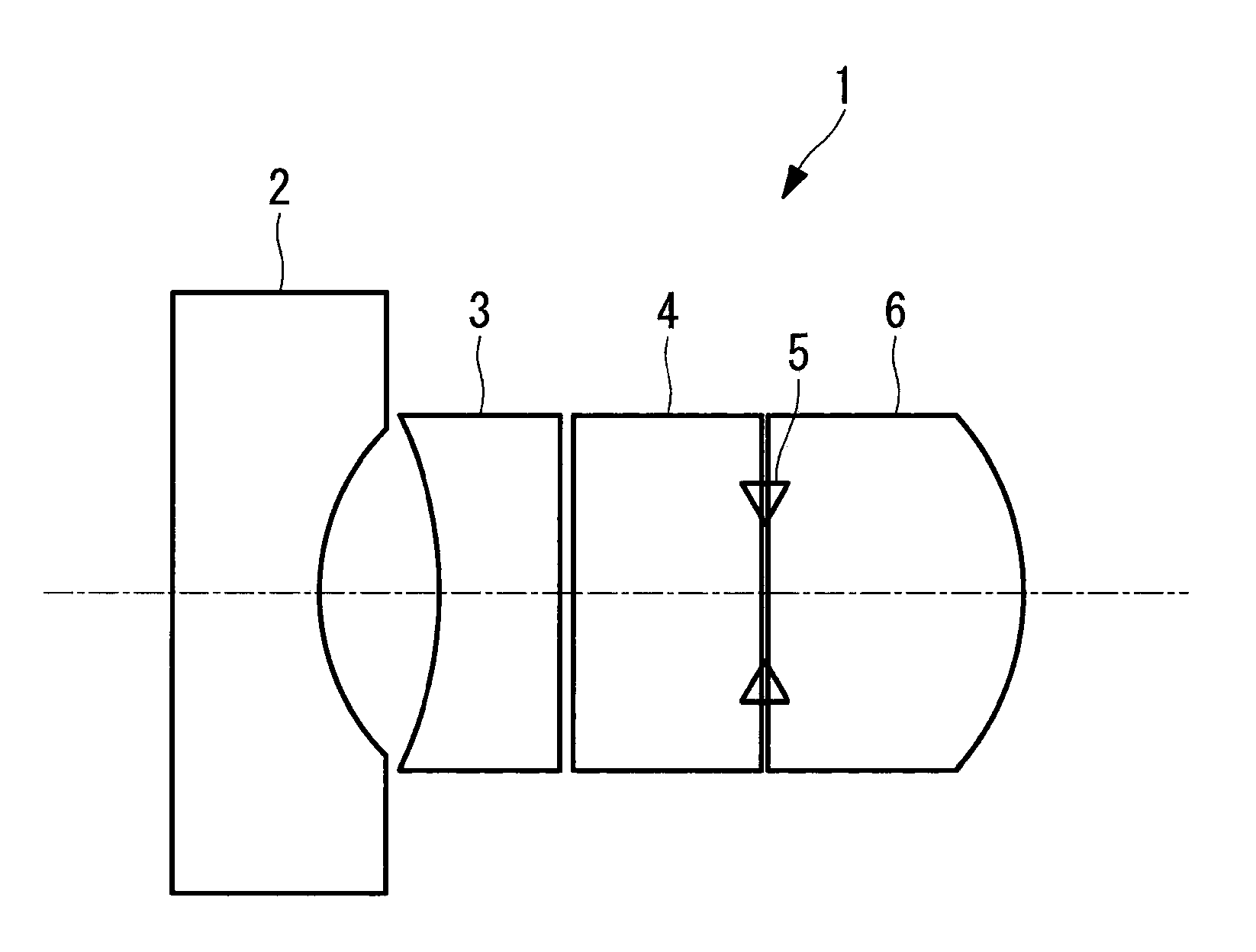
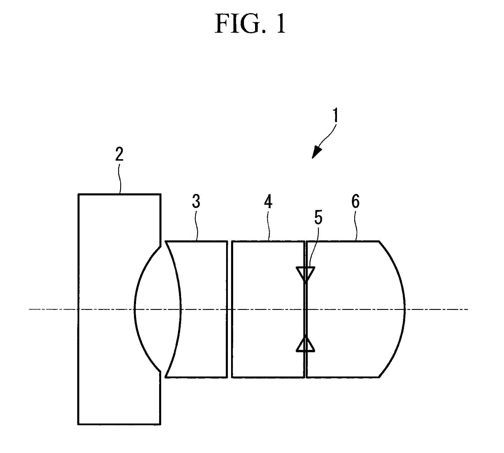
a technology of optical system and endoscope, which is applied in the field of endoscope objective optical system, can solve the problems of difficult configuration and difficult dimension, and achieve the effect of wide field angle reduced diameter of endoscope insertion portion

Active Publication Date: 2014-07-22
OLYMPUS CORP
View PDF7 Cites 0 Cited by
  • Summary
  • Abstract
  • Description
  • Claims
  • Application Information

AI Technical Summary

Benefits of technology

The invention helps to reduce the size of an endoscope insertion and allows for a wider field of view.

Problems solved by technology

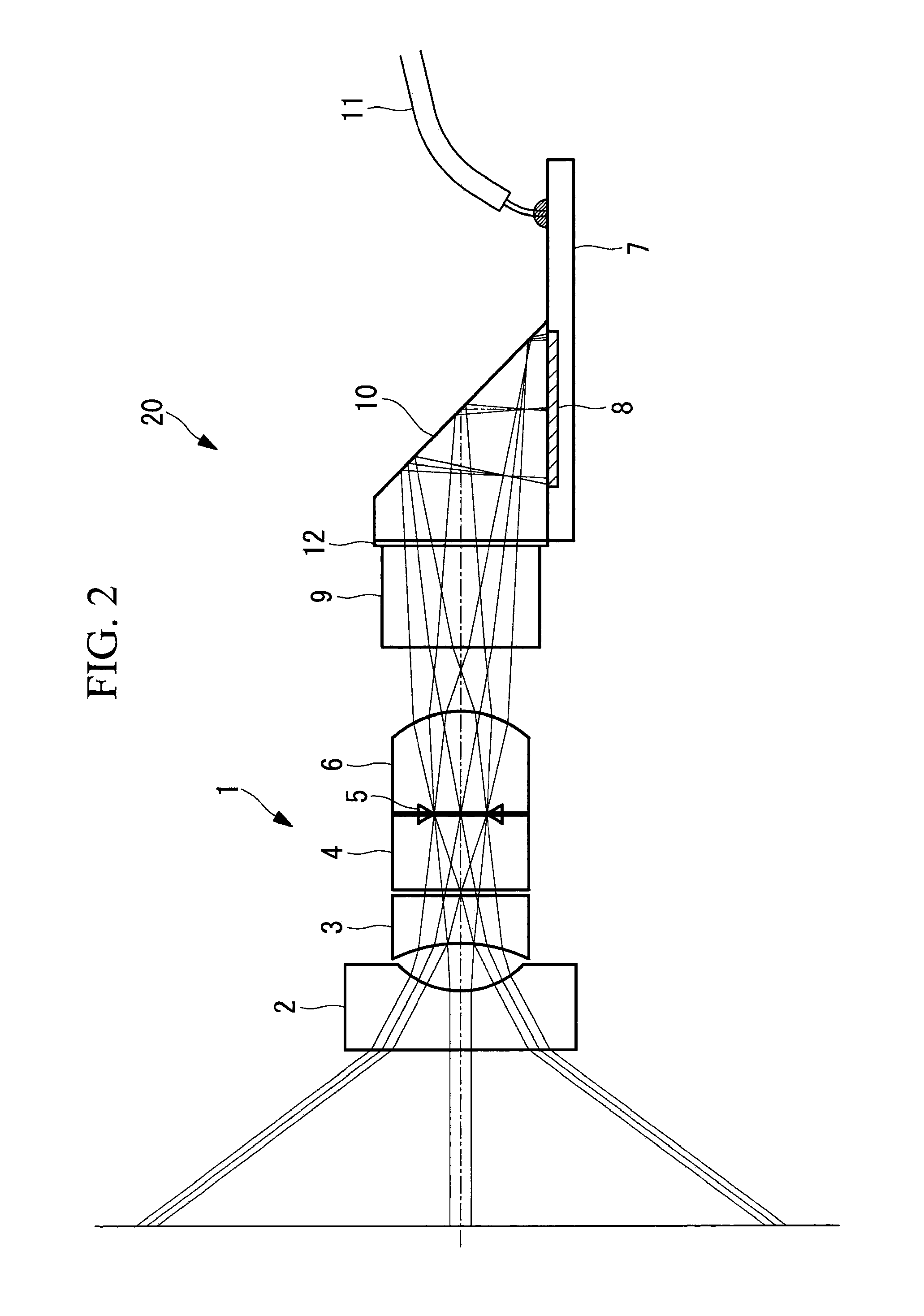
However, in an ultra-thin video-scope type endoscope (whose insertion portion has an outer diameter of, for example, 3 mm), it is dimensionally difficult that a substrate with a solid-state imaging element mounted thereon is arranged perpendicularly to the linearly extending optical axis of the objective optical system.
Therefore, such configuration is difficult to be realized by the objective optical system disclosed in PTL 1.

Method used


Image

  • Endoscope objective optical system
  • Endoscope objective optical system
  • Endoscope objective optical system

Examples


examples

[0039]Next, examples of the endoscope objective optical system 1 according to the above-described embodiment will be described below.

first example

[0040]FIG. 4 shows a lens array of an imaging optical system 20 including the endoscope objective optical system 1, according to a first example of the present embodiment, and Table 1 shows lens data. The lens data of Table 1 are normalized so that the focal length of the entire system is substantially equal to 1.

[0041]In the present example, the field angle is set to 108°.

[0042]

TABLE 1Surface numberrdnνObject∞56.5771∞0.65063091.768271.7921.0014060.48137013−2.9448120.62234261.88299740.7651074∞0.0575∞0.8486491.5211366.56∞0STO∞0.02828838∞09∞1.1315321.88299740.76510710−1.3069190.735855111∞1.1315321.5163364.14202212∞0.05657661.5164.1413∞2.4808841.6106150.214∞0

[0043]Further, in the present example, the specification values of the lenses are as follows.

[0044]fab=−0.849

[0045]f=0.988

[0046]fa=−3.335

[0047]fb=−1.304

[0048]fe=1.48

[0049]Na=1.7682

[0050]Nb=1.882997

second example

[0051]FIG. 5 shows a lens array of an imaging optical system 20 including the endoscope objective optical system 1, according to a second example of the present embodiment, and Table 2 shows lens data. The lens data of Table 2 are normalized so that the focal length of the entire system is substantially equal to 1.

[0052]In the present example, the field angle is set to 100°.

[0053]

TABLE 2Surface numberrdnνObject∞53.8551∞0.61932841.768271.7920.95322720.3733∞0.80781971.5211366.54∞0.1395−2.8031340.59240111.88299740.7651076∞0STO∞0.026927328∞09∞1.0770931.88299740.76510710−1.1497970.705495911∞1.0770931.5163364.14202212∞0.053854651.5164.1413∞2.3615261.6106150.214∞0

[0054]Further, in the present example, the specification values of the lenses are as follows.

[0055]fab=−0.722

[0056]f=0.989

[0057]fa=−1.241

[0058]fb=−3.175

[0059]fe=1.302

[0060]Na=1.7682

[0061]Nb=1.882997


PUM


Abstract

The diameter of an endoscope insertion portion is reduced, and a wide field angle of an endoscope insertion portion is obtained. An endoscope objective optical system includes, from an object side, a first lens formed of a plano-concave lens having a concave surface facing an image side, a second lens formed of a plano-concave lens having a concave surface facing the object side, an aperture stop, and a third lens formed of a plano-convex lens having a plane surface facing the object side, and satisfies0.7≦|fab / f|0.91.7≦|fe / fab|≦22≦fb / fa≦4where f: focal length of the entire system; fa: focal length of the first lens; fb: focal length of the second lens; fe: represents focal length of the third lens; fab: combined focal length from the first lens to the second lens.

Description

TECHNICAL FIELD[0001]The present invention relates to an endoscope objective optical system.BACKGROUND ART[0002]Conventionally, in order to obtain a lens system suitable for use of a solid-state imaging element, it is known to use an objective optical system which has a long back focus and a small size and which provides improvements in optical performance, such as an improvement in color reproducibility and a satisfactory correction of the image field curvature (see, for example, PTL 1).[0003]The objective optical system disclosed in PTL 1 is used for forming an object image on a solid-state imaging element arranged on a linear optical axis. Therefore, a prism, and the like, which bends the optical axis, does not need to be arranged between the objective optical system and the solid-state imaging element, and hence a certain length of back focus is sufficient for the formation of the object image.CITATION LISTPatent Literature[0004]{PTL 1} Japanese Unexamined Patent Application, Pu...

Claims


Application Information

Patent Timeline
Patent Type & Authority Patents(United States)
IPC IPC(8): G02B13/04A61B1/00A61B1/05G02B23/24G02B23/26
CPCG02B23/243A61B1/00A61B1/00163A61B1/051A61B1/00188A61B1/002G02B9/12
Inventor MORITA, KAZUO
Owner OLYMPUS CORP
Learn More