Arm for a pair of glasses

Active Publication Date: 2012-11-15
SILHOUETTE INT SCHMIED
View PDF7 Cites 2 Cited by
  • Summary
  • Abstract
  • Description
  • Claims
  • Application Information

AI Technical Summary

Benefits of technology

[0003]The invention is therefore based on the object of implementing an arm for a pair of glasses of the type described at the beginning so that the arm joint can be designed for at least one preferred bending direction while maintaining a simple structure.
[0004]The invention achieves the stated object in that the plastic envelope has a wall thickness which differs around the circumference and determines the bending resistance of the arm joint with respect to at least one predefined bending axis,
[0005]Since the bending resistance of the elastomeric plastic envelope is a function, inter alia, of the thickness of the plastic envelope, a preferred bending axis for the arm joint can be predefined by the provision of different wall thicknesses around the circumference, so that in a simple manner the coiled spring of the arm joint can be used for pressing the arm cheek against the head of the glasses wearer with an appropriate pre-tension, and preferably with a higher bending stiffness of the arm joint outside the preferred bending direction. In addition, the plastic envelope absorbs a part of the forces occurring between the arm sections, so that a composite effect results between the coiled spring and the plastic envelope, which is advantageous for the arm stress. This is true in particular if the coiled spring is extrusion coated using an elastomeric plastic.

Problems solved by technology

Simple structural conditions do result with the aid of coiled springs as the arm joints, however, the preferred joint axes of an arm of a pair of glasses cannot be taken into consideration by the bending resistance of a coiled spring, which is equal in all directions.
However, this has the disadvantage that the structural expenditure and the space requirement increase with the provision of multiple parallel coiled springs.

Method used


Image

  • Arm for a pair of glasses
  • Arm for a pair of glasses
  • Arm for a pair of glasses

Examples


Embodiment Construction

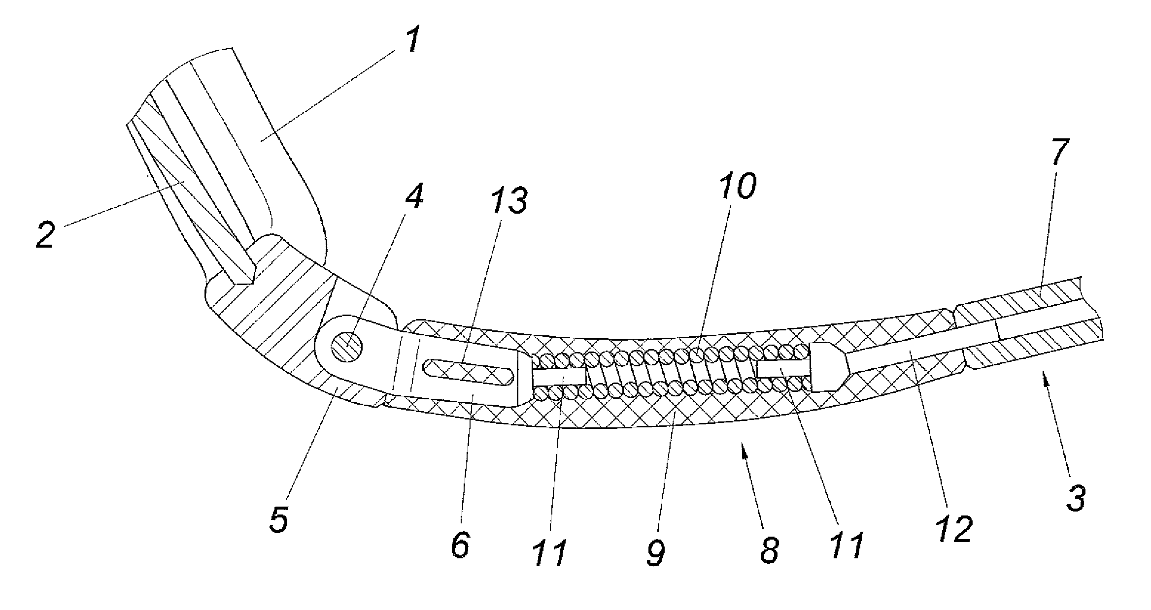
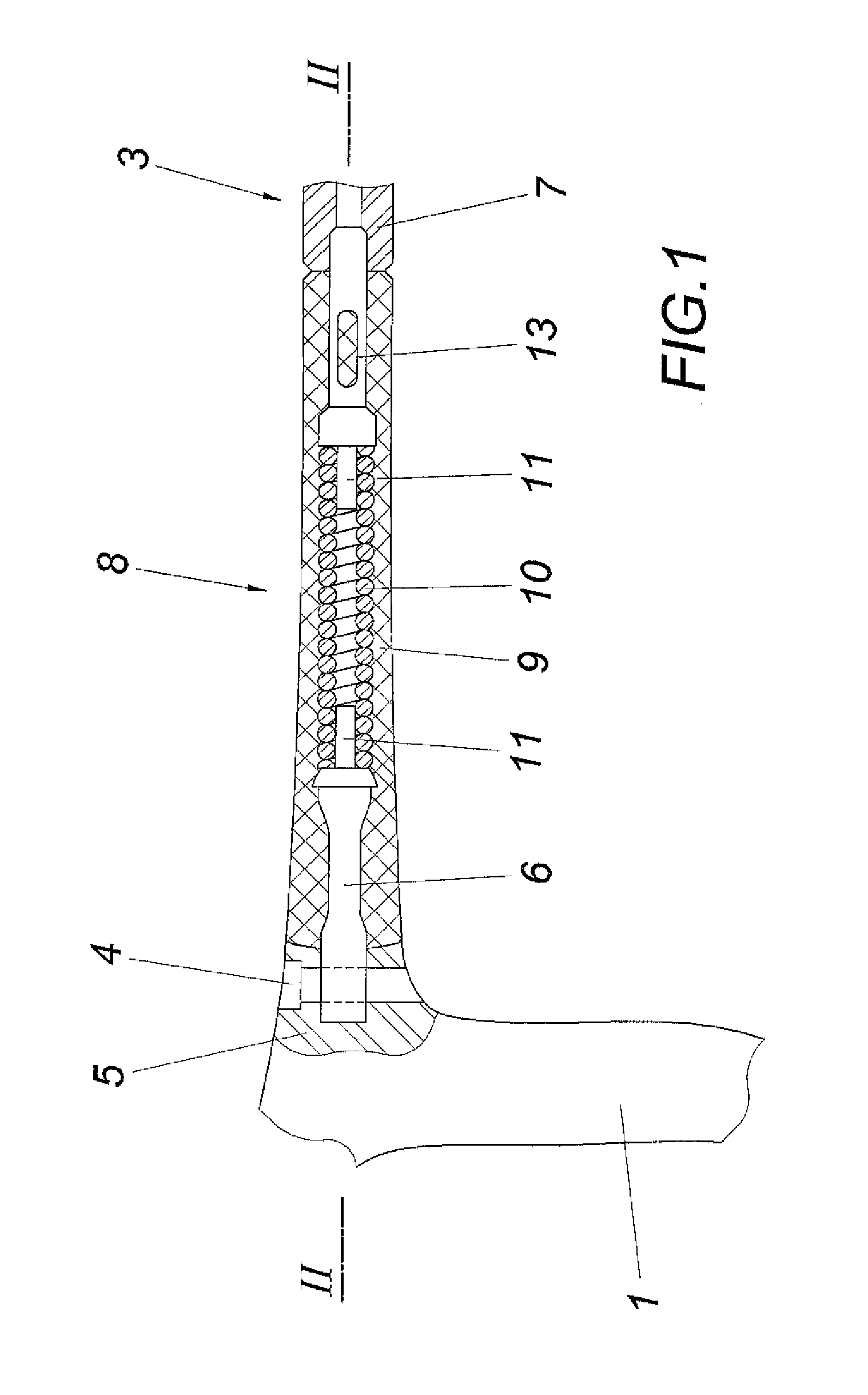
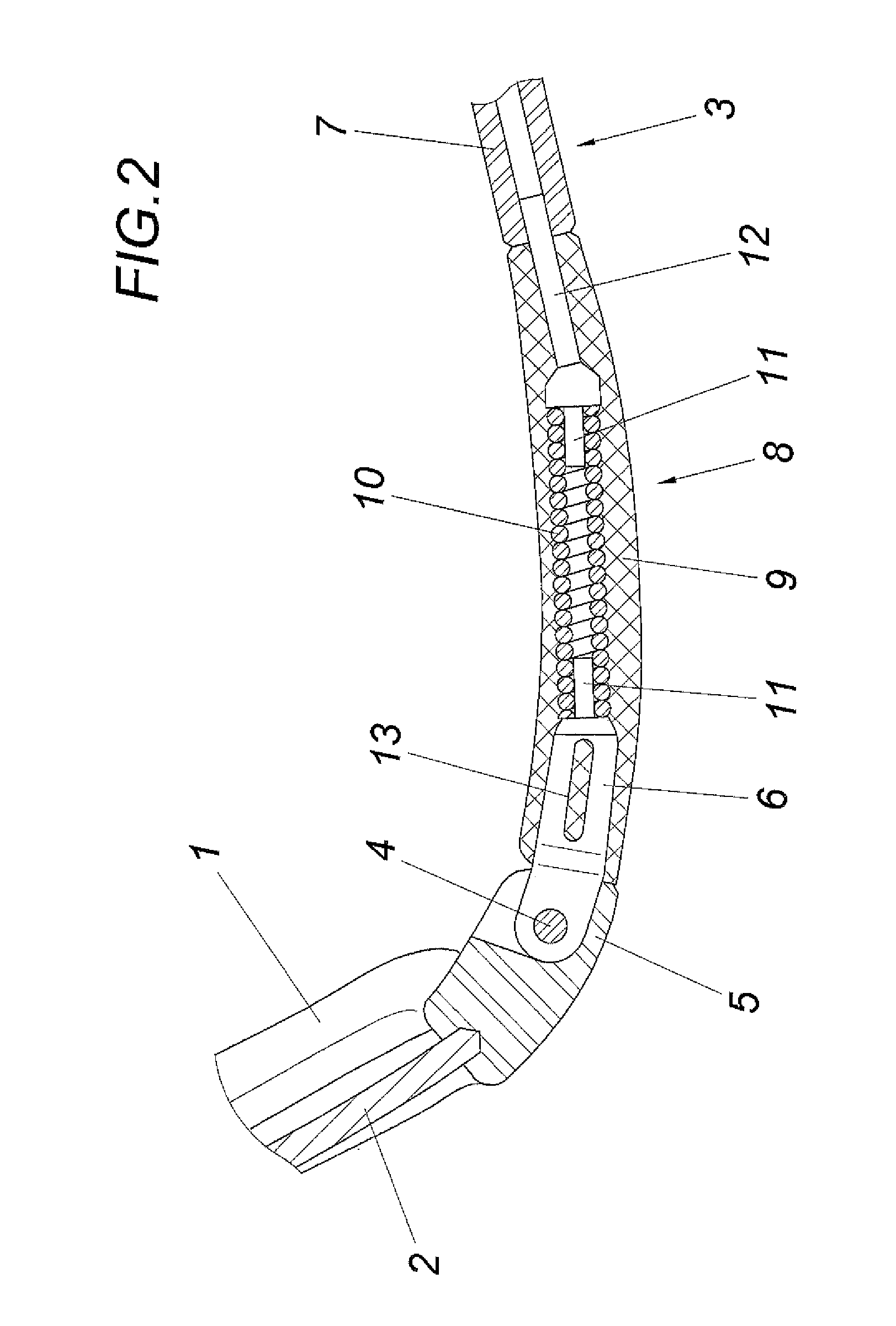
[0009]The illustrated pair of glasses has a frame 1 for glasses lenses 2 and two arms 3, which are linked via a hinge joint 4 to arm cheeks 5 of the frame 1. The arm section 6 formed by the arm-side hinge part is connected to the remaining arm section 7 via a resilient arm joint 8, which comprises a coiled spring 10 extrusion coated by a plastic envelope 9. The arrangement is made so that the coiled spring 10 is supported on plug attachments 11 of the hinge-side arm section 6 and the ear-side arm section 7, while the elastomeric plastic envelope 9 additionally encloses, beyond the plug attachments 11, the hinge part of the arm section 6, on one side, and the support insert 12 for the plug attachment 11 on the side of the arm joint 8 opposite to the hinge joint 4, on the other side. Because of the plastic which penetrates openings 13 of the arm section 6 and the support insert 12, a formfitting connection results between these structure parts and the plastic envelope 9, which can als...


PUM


Abstract

An arm (3) for a pair of glasses made of two sections (6, 7) is described, which are connected to one another via a coiled spring (10), which forms an arm joint (8) and is enveloped using an elastomeric plastic envelope (9). In order to achieve an advantageous bending behavior for the arm joint (8), it is proposed that the plastic envelope (9) have a differing wall thickness around the circumference, which determines the bending resistance of the arm joint (8) with respect to at least one predefined bending axis.

Description

FIELD OF THE INVENTION[0001]The invention relates to an arm for a pair of glasses made of two sections, which are connected to one another via a coiled spring, which forms an earpiece joint and is enveloped using an elastomeric plastic envelope.DESCRIPTION OF THE PRIOR ART[0002]In order to improve the hold of a pair of glasses on the head of a glasses wearer, equipping the pair of glasses with spring arms is known, which press with an appropriate resilient pre-tension against the head of a glasses wearer. For this purpose, providing an arm joint in the form of a coiled spring between the arms and the arm cheeks of the glasses has already been proposed (DE 101 18 019 A1, DE 94 00 967 U1). In addition, the arms can be subdivided into two longitudinal sections (DE 94 00 967 U1), which are in turn connected to one another via a coiled spring. To connect the arm cheeks and the arms to the coiled springs, the arm cheeks and arms can coaxially engage using threaded attachments from opposin...

Claims


Application Information

Patent Timeline
IPC IPC(8): G02C5/16
CPCG02C5/16G02C2200/28G02C2200/16
Inventor FUCHS, GERHARDSPINDELBALKER, RUPERT
Owner SILHOUETTE INT SCHMIED
Why Eureka
Try Eureka