Rotor blade for a wind turbine

Inactive Publication Date: 2012-12-13
SIEMENS AG
View PDF4 Cites 8 Cited by
  • Summary
  • Abstract
  • Description
  • Claims
  • Application Information

AI Technical Summary

Benefits of technology

[0015]Generally, it is possible that the circumferentially extending connecting means is adjacently disposed to the radially outer or inner boarder of a respective connecting element with respect to the centre axis of the rotor blade. The concrete radial location of the circumferentially extending connecting means may lead to differences in the mechanical stability of the circumferentially connection of the respective connecting elements. Concerning a single connecting element, radially outer positions of the circumferentially arranged connecting means provide higher bending stiffness. Of course, the same applies to the connecting elements as well, i.e. the closer they are disposed in relation to the outer diameter of the blade root, the more stiffening they will behave.
[001

Problems solved by technology

Both approaches for strengthening respective bla

Method used


Image

  • Rotor blade for a wind turbine
  • Rotor blade for a wind turbine
  • Rotor blade for a wind turbine

Examples


Example

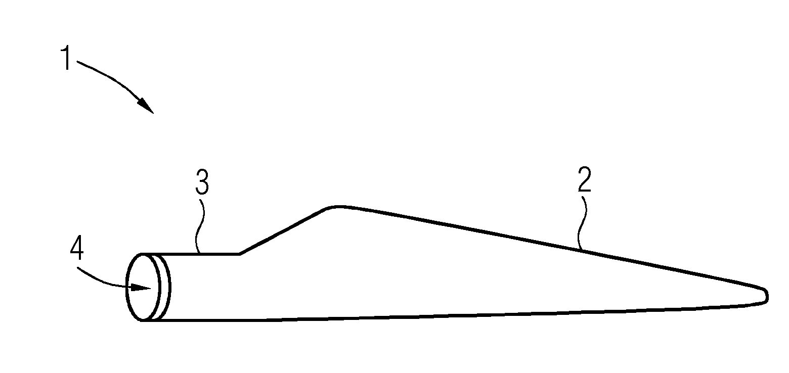
[0025]FIG. 1 shows a principle view of a rotor blade 1 according to an exemplary embodiment of the invention. The rotor blade 1 comprises an elongate base body 2 which axially ends in a respective blade root 3 having a respective circular root face side 4 (cf. FIG. 2). The rotor blade 1 is a hollow component made of a fibre-reinforced resin or cast material. The rotor blade 1 is attachable to a rotor hub of a wind turbine, particularly a direct drive wind turbine (not shown).

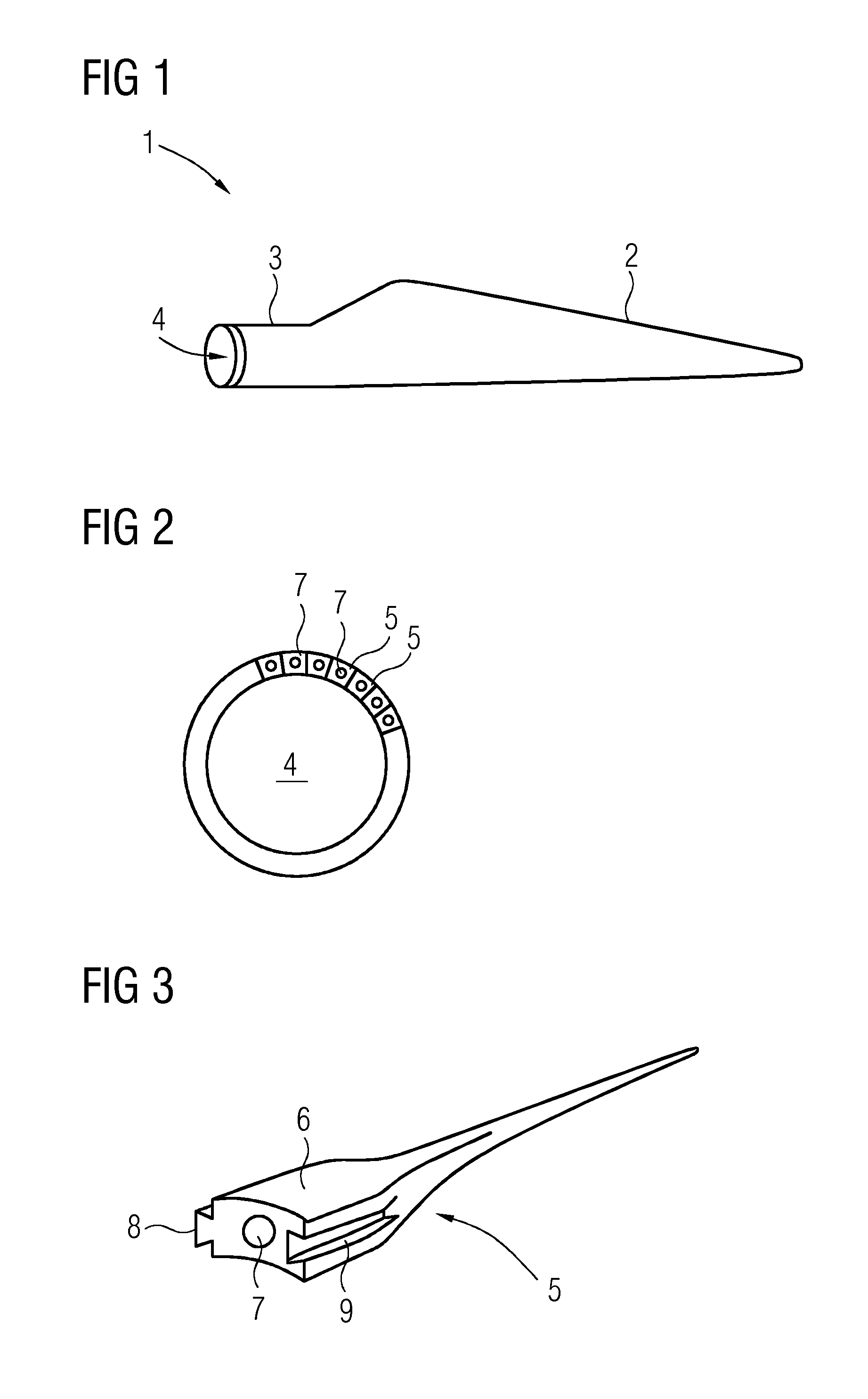
[0026]As is shown in FIG. 2, the face side 4 of the blade root 3 has a ring-like shape, whereby respective connecting elements 5 (cf. FIG. 3) are connected in circumferential direction so as to build a circumferentially closed ring-shape.

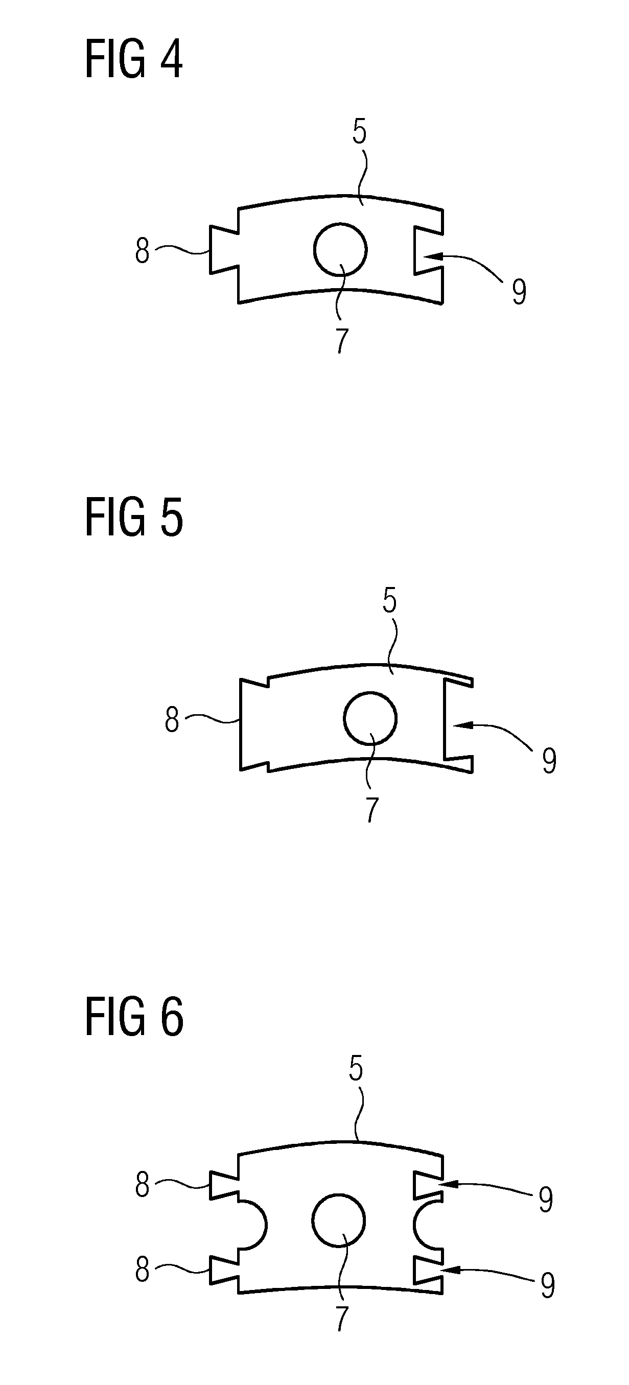
[0027]The connecting elements 5, which may also be denoted as studs, are shown in FIG. 3. A respective connecting element 5 comprises an axially extending base body 6 having an axially extending connecting portion 7 in the shape of a threaded hole. The axially extending connecti...


PUM


Abstract

A rotor blade for a wind turbine has an elongate blade base body with a plurality of connecting elements. Each connecting element comprises at least one axially extending connecting portion adapted to be connected with corresponding connecting portions of a rotor hub of the wind turbine. The connecting elements are connected in circumferential direction so as to build a closed ring-shape.

Description

CROSS REFERENCE TO RELATED APPLICATIONS[0001]This application claims priority of European Patent Office application No. 11169517.7 EP filed Jun. 10, 2011. All of the applications are incorporated by reference herein in their entirety.FIELD OF INVENTION[0002]A rotor blade for a wind turbine, having an elongate blade base body with a number of connecting elements each comprising at least one axially extending connecting portion adapted to be connected with corresponding connecting portions of a rotor hub of a wind turbine is providedBACKGROUND OF INVENTION[0003]Rotor blades for wind turbine are usually built as fibre-reinforced hollow composite structures. Hence, they are usually fabricated by impregnating respective aligned and orientated fibres or fibre clutches with a casting or resin material respectively. Thereby, removing of the cast rotor blade is oftentimes problematic since particularly in the region of the ring-like shaped root of the blade ovalisation may occur due to the s...

Claims


Application Information

Patent Timeline
IPC IPC(8): F01D5/30F01D5/22F01D5/02
CPCF03D1/001F03D1/065F03D1/0658F03D1/0691Y02E10/728F05B2240/80F05B2240/90Y02E10/721F05B2240/40F03D13/10Y02E10/72F03D1/0675
Inventor GROVE-NIELSEN, ERIK
Owner SIEMENS AG
Why Eureka
Try Eureka