Bumper arrangement

Pending Publication Date: 2022-02-17
BENTELER AUTOMOBILTECHNIK GMBH
View PDF4 Cites 1 Cited by
  • Summary
  • Abstract
  • Description
  • Claims
  • Application Information

AI Technical Summary

Benefits of technology

The invention is a bumper arrangement for vehicles that includes a crash box designed to absorb impact force during a collision. The arrangement includes a front wall and a rear wall with a depression in the front wall that acts as a trigger for the crash box. The depression is deep enough to touch the rear wall early on in the event of a collision, allowing the crash box to deform and absorb impact force. The arrangement also includes flexible upper and lower walls in the end regions that can compress and stretch, allowing for a more flexible response to different loads and reducing the need for larger crash boxes. The arrangement also includes a trapezoidal cross-section for the depression, which increases bending stiffness and allows for a more effective absorption of impact force. Overall, the invention provides a more effective and lightweight bumper arrangement for vehicles.

Problems solved by technology

These demands pose problems for the automobile industry.
For example, when the cross member deforms too easily in its end regions, e.g. because its upper and lower walls buckle or causing the cross member to even break off from the crash box when exposed to a high point load, then the crash box deforms only with a time delay.
As a result, the maximum permissible force and the resultant deformation work as product of force x path cannot be optimally utilized.

Method used


Image

  • Bumper arrangement
  • Bumper arrangement
  • Bumper arrangement

Examples


Embodiment Construction

[0038]Throughout all the Figures, same or corresponding elements may generally be indicated by same reference numerals. These depicted embodiments are to be understood as illustrative of the invention and not as limiting in any way. It should also be understood that the FIGS. are not necessarily to scale and that the embodiments may be illustrated by graphic symbols, phantom lines, diagrammatic representations and fragmentary views. In certain instances, details which are not necessary for an understanding of the present invention or which render other details difficult to perceive may have been omitted.

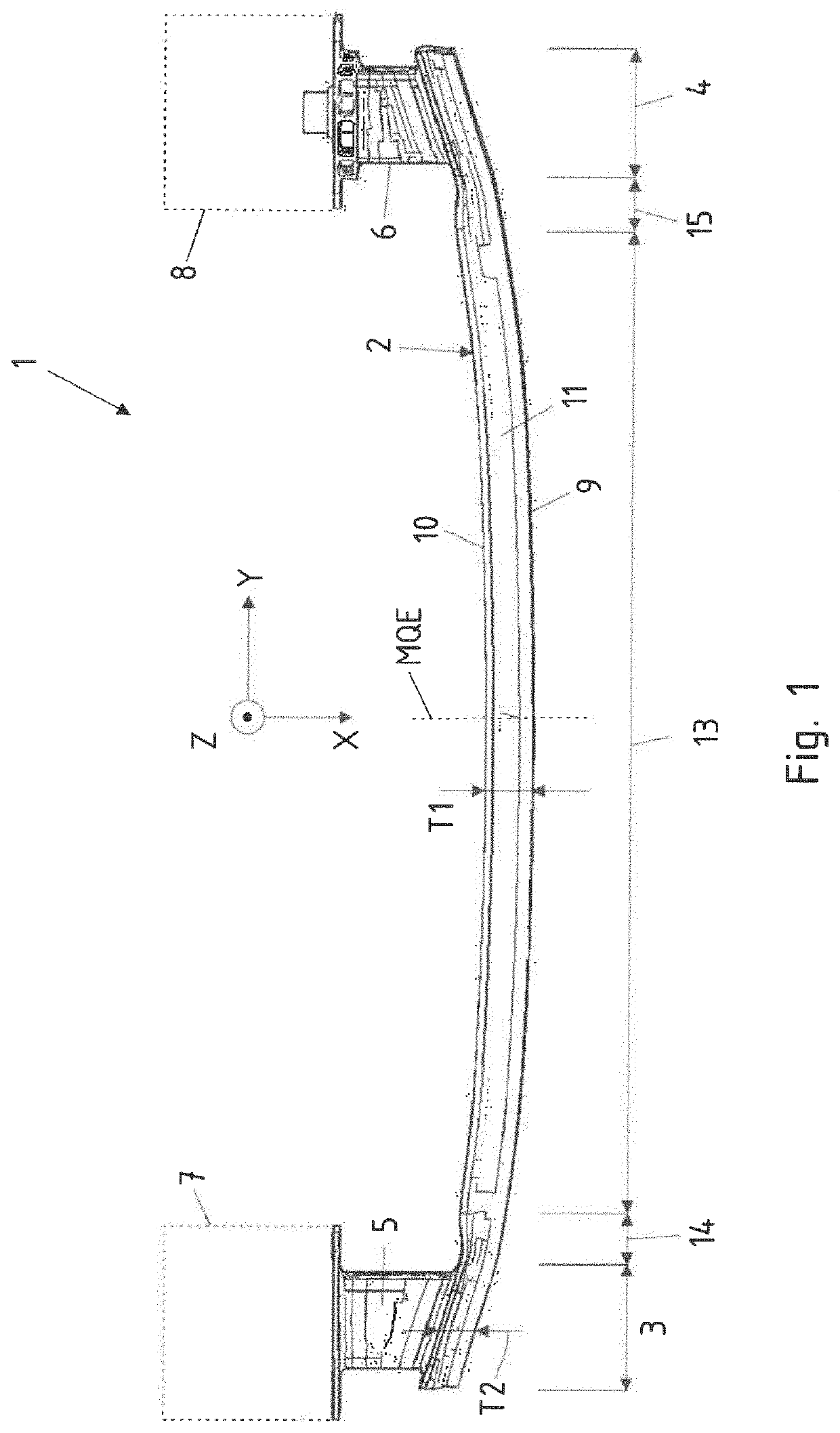
[0039]Turning now to the drawing, and in particular to FIG. 1, there is shown a plan view of a bumper arrangement according to the invention, generally designated by reference numeral 1 and including a cross member 2 made from an extruded hollow profile. The cross member 2 has end regions 3, 4, via which the cross member 2 is attached to deformation elements 5, 6. The deformation ele...


PUM


Abstract

A bumper arrangement includes a cross member and two deformation elements for arrangement between end regions of the cross member and longitudinal members of a motor vehicle. The cross member is hollow with a front and rear walls and upper and lower walls. The front wall has a depression extending in longitudinal direction of the cross member. The depression has a deepest region extending at a distance from the rear wall. The upper and lower walls of the cross member each have in the end regions a further depression which extends in longitudinal direction of the cross member, so that the upper wall and the lower wall are more corrugated in the end regions than in a central region of the cross member, so that the distance between the front wall and the rear wall in the end regions is smaller than in a central region of the cross member.

Description

CROSS-REFERENCES TO RELATED APPLICATIONS[0001]This application claims the priority of German Patent Applications, Serial No. 10 2020 121 326.3, filed Aug. 13, 2020, and Serial No. 10 2020 127 736.9, filed Oct. 21, 2020, pursuant to 35 U.S.C. 119(a)-(d), the disclosure(s) of which is / are incorporated herein by reference in its entirety as if fully set forth herein.BACKGROUND OF THE INVENTION[0002]The invention relates to a bumper arrangement.[0003]The following discussion of related art is provided to assist the reader in understanding the advantages of the invention, and is not to be construed as an admission that this related art is prior art to this invention.[0004]A bumper arrangement typically includes a cross member and two deformation elements (crash boxes) for installation to the front side and rear side of a motor vehicle, e.g. car, to absorb the impact energy of smaller impact. The deformation elements are hereby installed between end portions of the cross member and longit...

Claims


Application Information

Patent Timeline
IPC IPC(8): B60R19/34B60R19/18
CPCB60R19/34B60R2019/1806B60R19/18B60R2019/182
Inventor AALBERG, JOHANNES
Owner BENTELER AUTOMOBILTECHNIK GMBH
Why Eureka
Try Eureka