Channel feedback for coordinated multi-point transmissions

a multi-point transmission and channel feedback technology, applied in the field of wireless communication, can solve the problem that other transmission points are regarded as co-channel interferen

Active Publication Date: 2012-11-15
TEXAS INSTR INC
View PDF6 Cites 143 Cited by
  • Summary
  • Abstract
  • Description
  • Claims
  • Application Information

AI Technical Summary

Benefits of technology

[0007]A method of Coordinated Multipoint (CoMP) communication between a base station has a plurality of points with at least one user equipment (UE). At least one UE receives at least one transmission from the base station having the plurality of points. This UE measures downlin

Problems solved by technology

In traditional wireless networks signals from other tran

Method used


Image

  • Channel feedback for coordinated multi-point transmissions
  • Channel feedback for coordinated multi-point transmissions
  • Channel feedback for coordinated multi-point transmissions

Examples


example 1

[0040]UEreportsCell1:RI_1,PMI_1,CQI_1…CellN:RI_N,PMI_N,CQI_N.

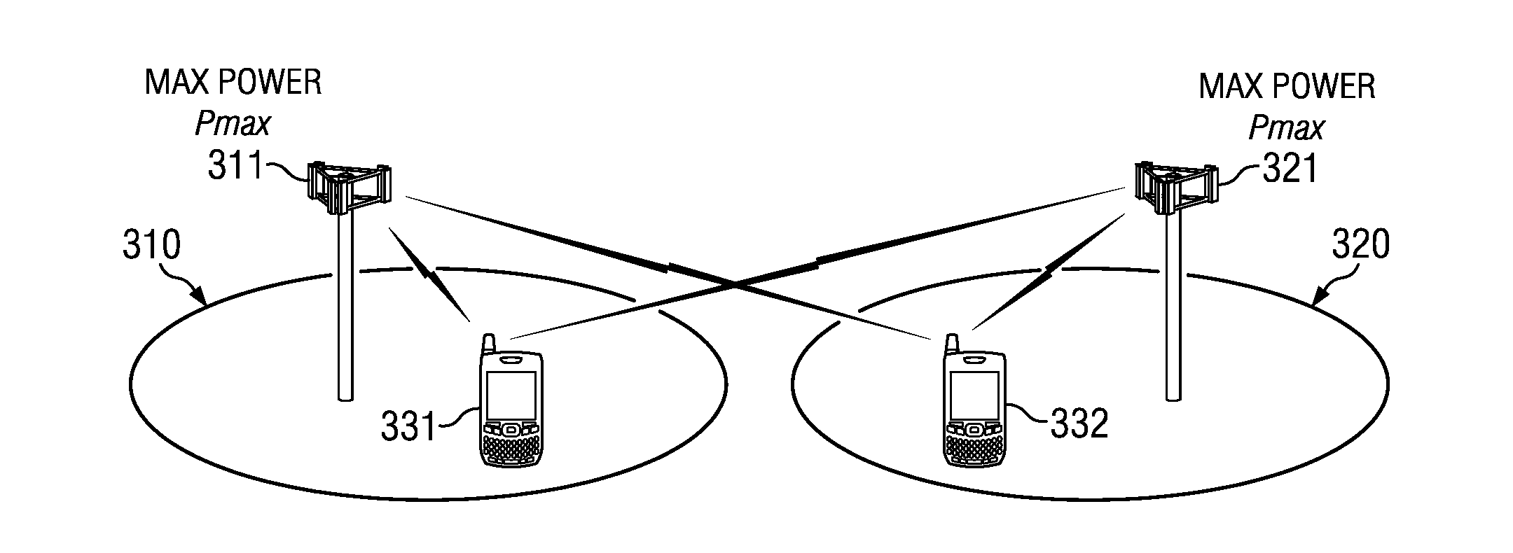
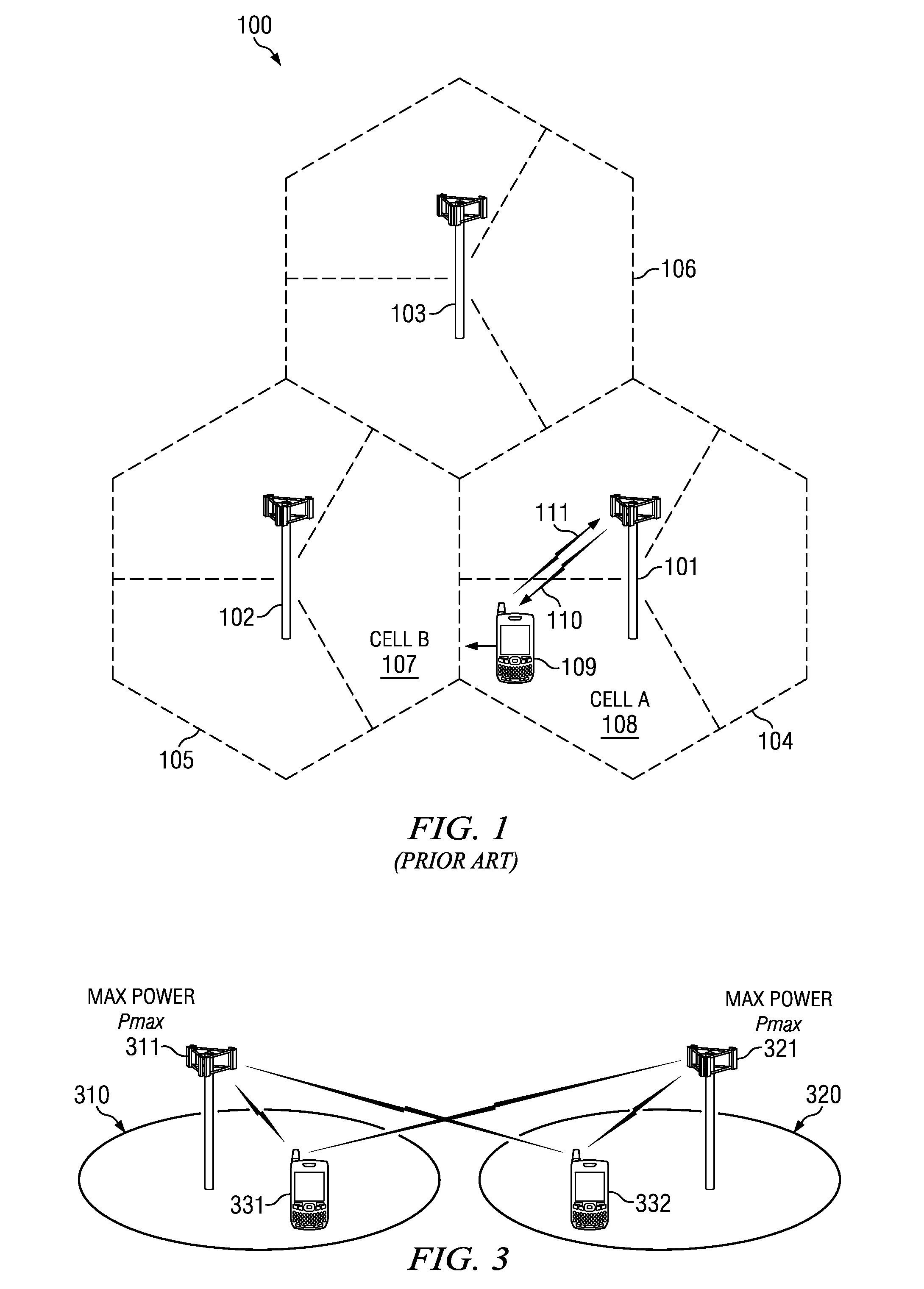
[0041]Assume N=2 RRH distributed alternatively along the highway and configured with different CSI-RS sets. As a UE moves along the highway, the network shall compare the CSI feedback received from the two RRHs to determine which RRH to serve the UE.

example 2

[0042]UEreportsCell1:PMI_1,CQI_1…CellN:PMI_N,CQI_N.

[0043]Here RI is fixed or semi-statically configured such as 1 for all cells. This may be more appropriate for high-speed railroad scenario where rank-1 SU-MIMO transmission is most robust.

example 3

[0044]UEreportsCell1:RI_1,PMI_1,CQI_1Cell2:PMI_2,CQI_2…CellN:PMI_N,CQI_N.

[0045]Here rank adaptation is only supported for a principle cell while all other cells assume either (1) a fixed rank transmission such as rank-1 or (2) a rank value equivalent to the first cell where RI_k=R—1 for k=2, . . . N.


PUM


Abstract

A method of Coordinated Multipoint (CoMP) communication between a base station has a plurality of points with at least one user equipment (UE). At least one UE receives at least one transmission from the base station having the plurality of points. This UE measures downlink channel state information for each of the plurality of points including a rank indicator (RI), a precoding matrix indicator (PMI) and a channel quality indicator (CQI). This UE transmits the downlink channel station information in an uplink feedback channel to the base station.

Description

CLAIM OF PRIORITY[0001]This application claims priority under 35 U.S.C. 119(e)(1) to U.S. Provisional Application No. 61 / 483,843 filed May 9, 2011 and U.S. Provisional Application No. 61 / 522,350 filed Aug. 11, 2011.TECHNICAL FIELD OF THE INVENTION[0002]The technical field of this invention is wireless communication such as wireless telephony.BACKGROUND OF THE INVENTION[0003]The present embodiments relate to wireless communication systems and, more particularly, to the CoMP or Coordinated Multi-Point Transmission.[0004]The term CoMP stands for Coordinated Multi-Point Transmission. In CoMP multiple transmission points such as macro evolved Node B (eNB), pico eNB, femto eNB, remote radio heads (RRHs), distributed antennas, other wireless transmission entity or combinations coordinate with each other to jointly optimize downlink transmission signals to user equipment (UE). This cooperation includes beamforming vectors, transmission power and / or scheduling decisions. In traditional wirel...

Claims


Application Information

Patent Timeline
IPC IPC(8): H04W72/08H04W24/00
CPCH04B7/024H04B7/0626H04B7/0639H04B7/063H04B7/0647H04B7/0636H04L5/006
Inventor CHEN, RUNHUACHANDRASEKHAR, VIKRAMONGGOSANUSI, EKO
Owner TEXAS INSTR INC
Why Eureka
Try Eureka