Estimation of a position and orientation of a frame used in controlling movement of a tool

a technology of positioning and positioning, applied in the field of robotic systems, can solve the problems of difficult to achieve precise control of surgical instruments, jeopardizing the successful completion of a procedure being performed on the patient, and a patient being treated at the time by the medical robotic system

Active Publication Date: 2012-11-15
INTUITIVE SURGICAL OPERATIONS INC
View PDF9 Cites 92 Cited by
  • Summary
  • Abstract
  • Description
  • Claims
  • Application Information

AI Technical Summary

Benefits of technology

[0008]This and additional objects are accomplished by the various aspects of the present invention, wherein briefly stated, one aspect is a robotic system comprising: a master control device having a master frame; an image capturing system having an image frame whose position and orientation relative to a fixed frame is determinable through one or more image frame transforms; a tool disposed within a field of view of the image capturing system and having a tool frame whose position and orientation relative to the fixed frame is determinable through one or more tool frame transforms; and at least one processor programmed to identify pose indicating points of the tool from information in one or more images captured by the image capturing system, determine an estimated transform for an unknown one of the image and tool frame transforms by using the identified pose indicating points and known ones of the image and tool frame transforms, update a master-to-tool transform by using the estimated and known ones of the image and tool frame transforms, and command movement of the tool in response to movement of the master control ...

Problems solved by technology

When the position and orientation of one of the frames is unknown, however, precise control of the surgical instrument may be difficult to achieve so that the safety...

Method used


Image

  • Estimation of a position and orientation of a frame used in controlling movement of a tool
  • Estimation of a position and orientation of a frame used in controlling movement of a tool
  • Estimation of a position and orientation of a frame used in controlling movement of a tool

Examples


Embodiment Construction

[0024]Although the following example describes application of the present invention to a medical robotic system, it is to be appreciated that the present invention is not to be so limited. In particular, the present invention is applicable to robotic systems in general and should be accorded its full scope according to the attached claims.

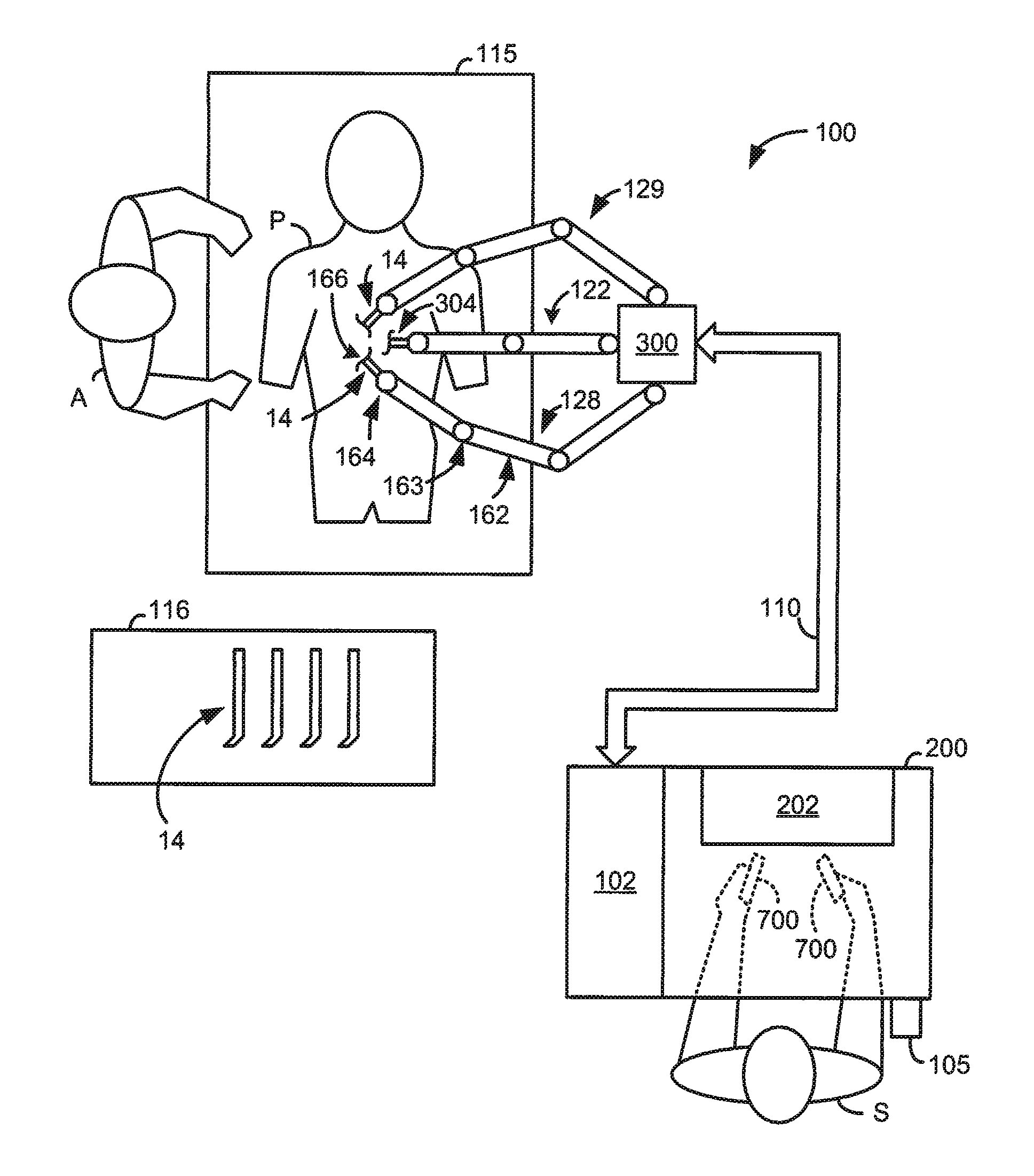
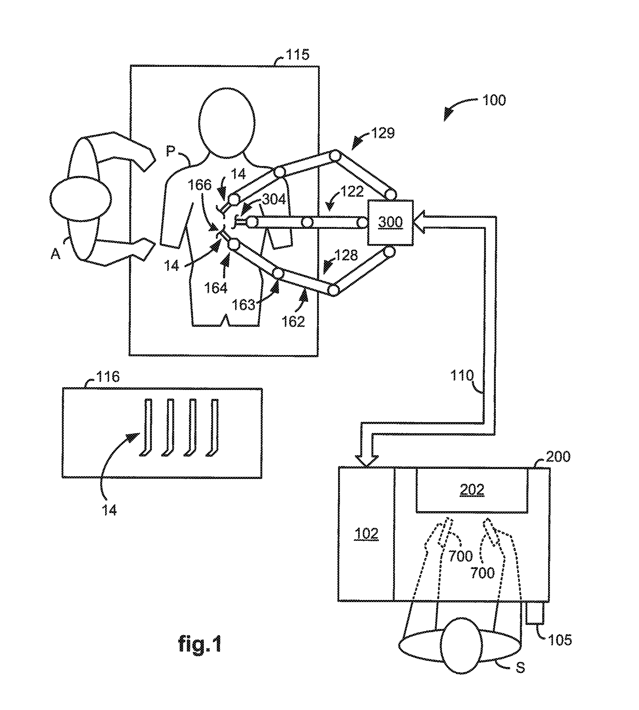
[0025]FIG. 1 illustrates, as an example, a top view of an operating room employing a medical robotic system 100. The medical robotic system in this case is a minimally invasive robotic surgical system including a workstation 200 utilized by a surgeon (“S”) while performing a medical procedure, such as a diagnostic or surgical procedure, with assistance from one or more assistants (“A”), on a patient (“P”) who is lying face up on an operating table 115.

[0026]The workstation 200 includes a 3-D display 202 for displaying a 3-D image of a surgical or work site to the surgeon, left and right master control devices 700, 700, a foot pedal 105, and a proce...


PUM


Abstract

A robotic system includes a camera having an image frame whose position and orientation relative to a fixed frame is determinable through one or more image frame transforms, a tool disposed within a field of view of the camera and having a tool frame whose position and orientation relative to the fixed frame is determinable through one or more tool frame transforms, and at least one processor programmed to identify pose indicating points of the tool from one or more camera captured images, determine an estimated transform for an unknown one of the image and tool frame transforms using the identified pose indicating points and known ones of the image and tool frame transforms, update a master-to-tool transform using the estimated and known ones of the image and tool frame transforms, and command movement of the tool in response to movement of a master using the updated master-to-tool transform.

Description

FIELD OF THE INVENTION[0001]The present invention generally relates to robotic systems and in particular, to estimation of a position and orientation of a frame used in controlling operator commanded movement of a tool.BACKGROUND OF THE INVENTION[0002]Medical robotic systems such as those used in performing minimally invasive surgical procedures offer many benefits over traditional open surgery techniques, including less pain, shorter hospital stays, quicker return to normal activities, minimal scarring, reduced recovery time, and less injury to tissue. Consequently, demand for minimally invasive surgery using such medical robotic systems is strong and growing.[0003]Examples of medical robotic systems include the DaVinci® Surgical System, the daVinci S® Surgical System, and the DaVinci® Si HD™ Surgical System from Intuitive Surgical, Inc., of Sunnyvale, Calif. Each of these systems includes a surgeon's workstation, a patient-side cart, a high performance three-dimensional (“3-D”) vi...

Claims


Application Information

Patent Timeline
IPC IPC(8): B25J13/08B25J19/04
CPCA61B19/2203A61B19/5212B25J9/1697A61B2019/5265B25J9/1689A61B2019/2223A61B90/361A61B34/37A61B2034/2065A61B34/30A61B34/25A61B34/35A61B34/74B25J13/08B25J19/04
Inventor ZHAO, TAOPRISCO, GIUSEPPE MARIASTEGER, JOHN RYANLARKIN, DAVID Q.
Owner INTUITIVE SURGICAL OPERATIONS INC
Why Eureka
Try Eureka