
Combustor nozzle and method for supplying fuel to a combustor

Active Publication Date: 2012-11-22
GENERAL ELECTRIC CO
View PDF18 Cites 16 Cited by
  • Summary
  • Abstract
  • Description
  • Claims
  • Application Information

AI Technical Summary

Benefits of technology

[0005]Aspects and advantages of the invention are set forth below in the following description, or may be obvious from the description, or may be learned through practice of the invention.

Problems solved by technology

If the liquid and / or gaseous fuel is not evenly mixed with the compressed working fluid prior to combustion, localized hot spots may form in the combustor.
The localized hot spots may increase the production of nitrous oxides in the fuel rich regions, while the fuel lean regions may increase the production of carbon monoxide and unburned hydrocarbons, all of which are undesirable exhaust emissions.
In addition, the fuel rich regions may increase the chance for the flame in the combustor to flash back into the nozzles and / or become attached inside the nozzles which may damage the nozzles.
However, the emulsified fuel, if not adequately dispersed, may result in flame instability and / or increased undesirable exhaust emissions.

Method used


Image

  • Combustor nozzle and method for supplying fuel to a combustor
  • Combustor nozzle and method for supplying fuel to a combustor
  • Combustor nozzle and method for supplying fuel to a combustor

Examples


Embodiment Construction

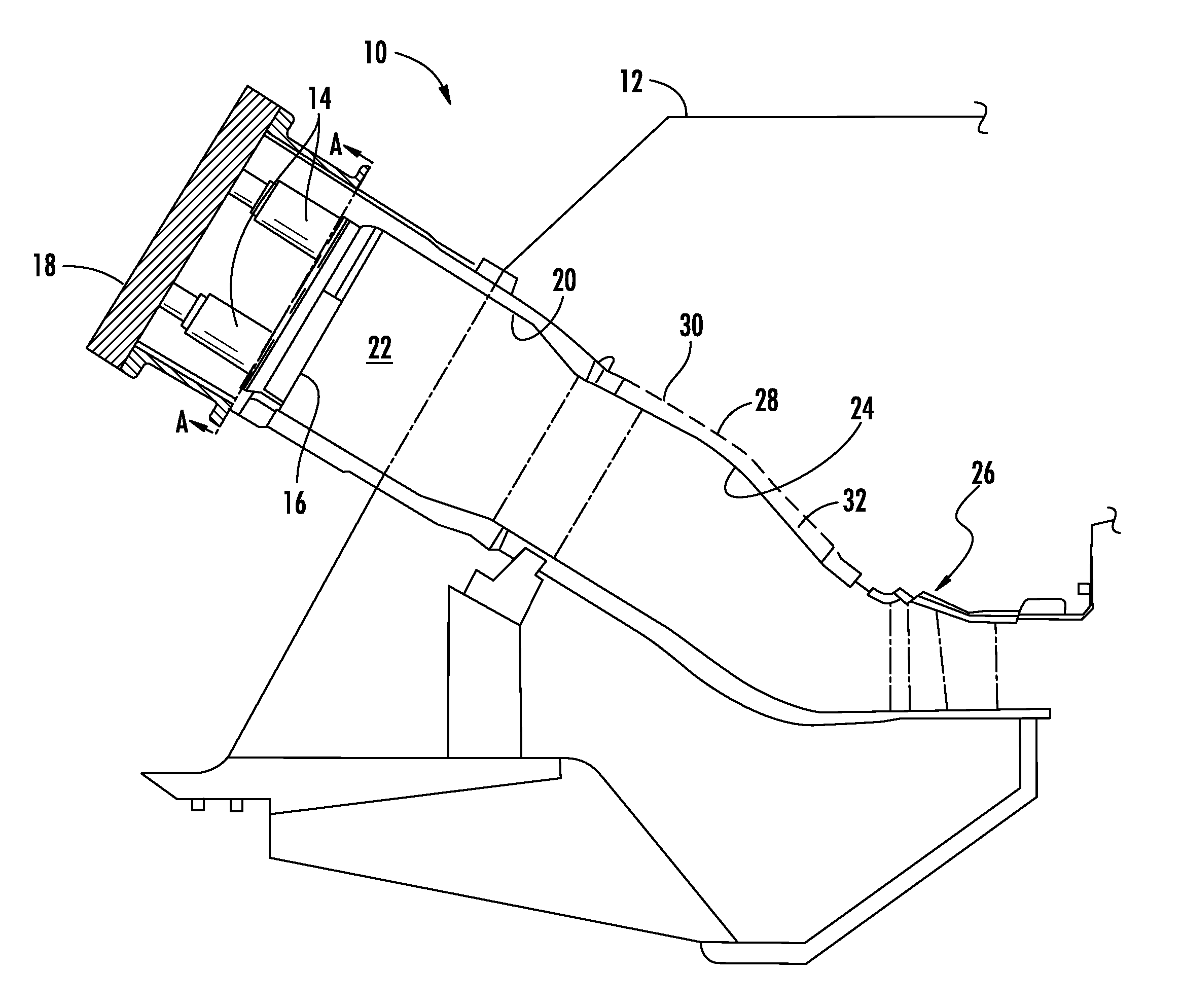
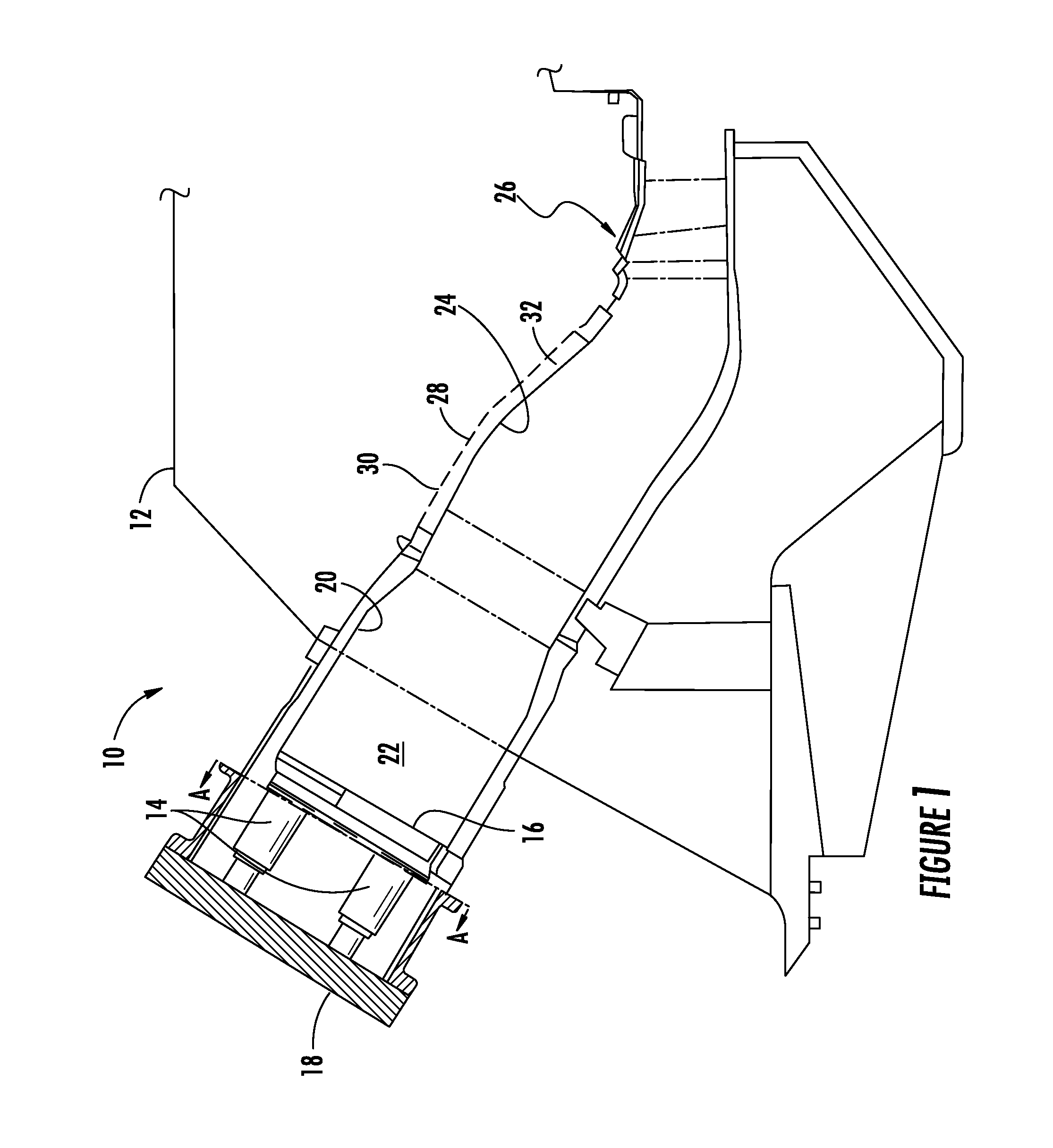
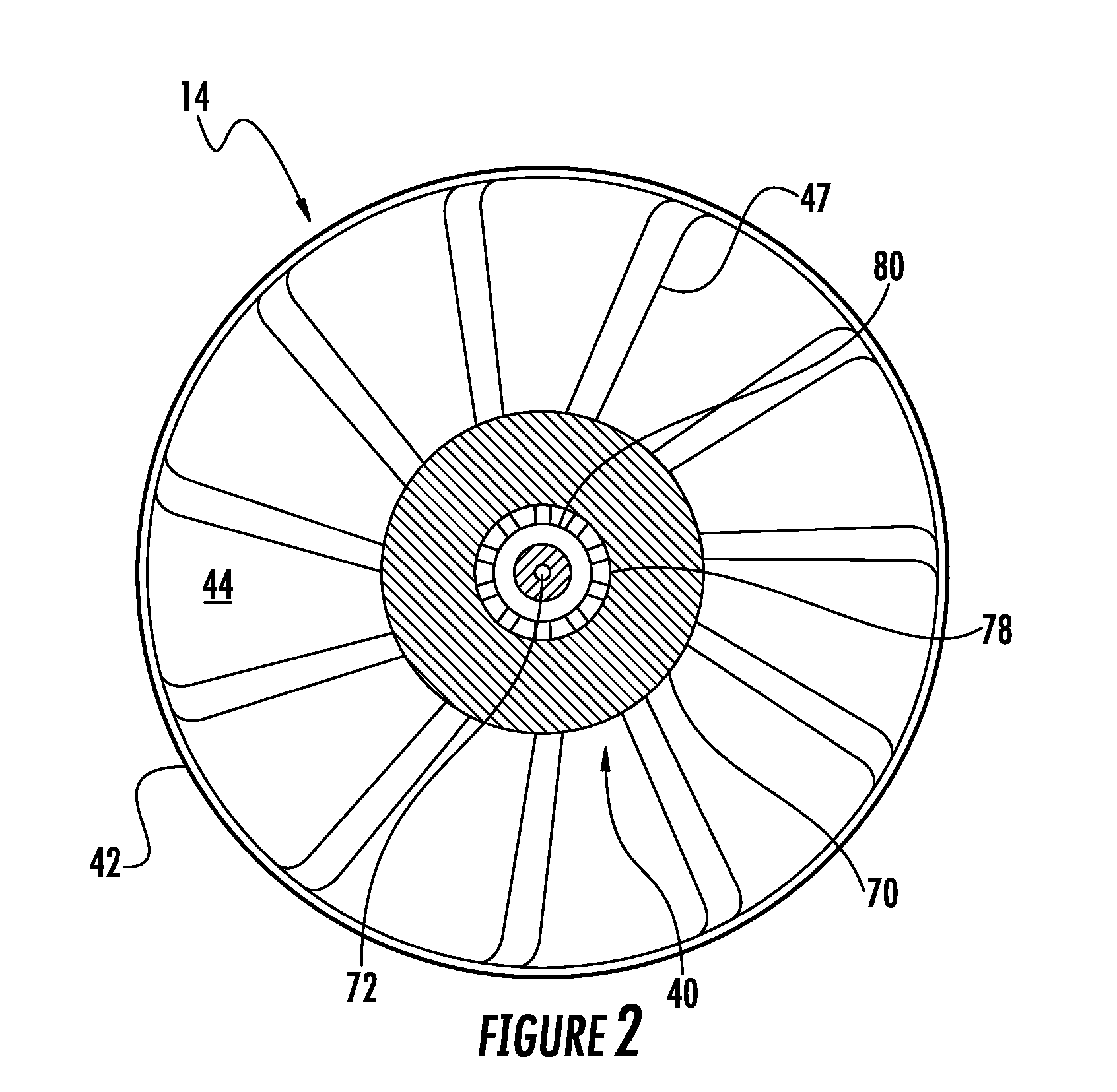
[0017]Reference will now be made in detail to present embodiments of the invention, one or more examples of which are illustrated in the accompanying drawings. The detailed description uses numerical and letter designations to refer to features in the drawings. Like or similar designations in the drawings and description have been used to refer to like or similar parts of the invention.

[0018]Each example is provided by way of explanation of the invention, not limitation of the invention. In fact, it will be apparent to those skilled in the art that modifications and variations can be made in the present invention without departing from the scope or spirit thereof. For instance, features illustrated or described as part of one embodiment may be used on another embodiment to yield a still further embodiment. Thus, it is intended that the present invention covers such modifications and variations as come within the scope of the appended claims and their equivalents.

[0019]Various embodi...


PUM


Abstract

A combustor nozzle includes a first and second liquid fuel passages that terminate at first and second fuel ports. A first diluent passage terminates at a first diluent outlet radially surrounding the second fuel ports. A second diluent passage terminates at a second diluent outlet between the first diluent outlet and the second fuel ports. A third diluent passage surrounds at least a portion of the first and second diluent passages. A method for supplying fuel to a combustor includes flowing a liquid fuel through a first fuel passage and flowing an emulsified liquid fuel through a second fuel passage. The method further includes flowing a first diluent through a shroud surrounding the second fuel passage to a first diluent passage surrounding at least a portion of the second fuel passage and flowing a second diluent through a second diluent passage radially disposed between the first diluent passage and the second fuel passage.

Description

FIELD OF THE INVENTION[0001]The present invention generally involves a combustor nozzle and a method for supplying fuel to a combustor. In particular embodiments of the present invention, the combustor nozzle may supply liquid and emulsified fuel to the combustor.BACKGROUND OF THE INVENTION[0002]Combustors are commonly used in industrial and commercial operations to ignite fuel to produce combustion gases having a high temperature and pressure. For example, an industrial gas turbine may include one or more combustors to generate power or thrust. A typical commercial gas turbine used to generate electrical power may include an axial compressor at the front, one or more combustors around the middle, and a turbine at the rear. Ambient air may be supplied to the compressor, and rotating blades and stationary vanes in the compressor progressively impart kinetic energy to the working fluid (air) to produce a compressed working fluid at a highly energized state. The compressed working flui...

Claims


Application Information

Patent Timeline
IPC IPC(8): F02C7/22
CPCF23C2900/07021F23D11/16F23R3/343F23L2900/07008F23L7/005
Inventor BOARDMAN, GREGORY ALLENMYERS, GEOFFREY DAVIDROSS, WILLIAM THOMAS
Owner GENERAL ELECTRIC CO
Learn More