
Carrying Case For Concealed Firearms

a concealed firearm and carrying case technology, applied in the direction of weapons, arms wearables, weapon components, etc., can solve the problems of limited access to the firearm, limited quick access or deployment, and limited user's choice of dress or comfor

Inactive Publication Date: 2012-11-22
BAXLEY CHARLES CLYDE
View PDF3 Cites 6 Cited by
  • Summary
  • Abstract
  • Description
  • Claims
  • Application Information

AI Technical Summary

Benefits of technology

[0008]The object of the present invention is to provide a carrying device that can completely conceal the firearm without revealing the shape or part of the firearm.
[0009]Another object of the present invention is to provide a carrying device that can be worn in plain sight. Thus, the user can dress in a manner of choice or comfort.
[0010]Still another object of the present invention is to provide a carrying device that provides features to ensure good safety practice, thus reducing possibility of accidental discharge.

Problems solved by technology

This is generally accomplished by apparel that must be worn at all times, thus limiting the user's choice of dress or comfort.
Some require placement inside or underneath apparel that must be removed or disengaged before accessing the weapon, thus limiting quick access or deployment.
Although there are previous examples that do not reveal the shape or part of the weapon, the access they provide to the firearm is limited because the firearm is fully enclosed via zipper or other closure.
These require the user to open the zipper or closure and reach inside to grip the weapon for withdrawal, thus limiting quick access and deployment.
In some instances the trigger may be exposed inside the enclosure increasing the possibility of an accidental discharge when attempting to deploy the weapon.
The user may not be able to grasp the handgun properly because the handgun may not be secured in place.

Method used


Image

  • Carrying Case For Concealed Firearms
  • Carrying Case For Concealed Firearms
  • Carrying Case For Concealed Firearms

Examples


Embodiment Construction

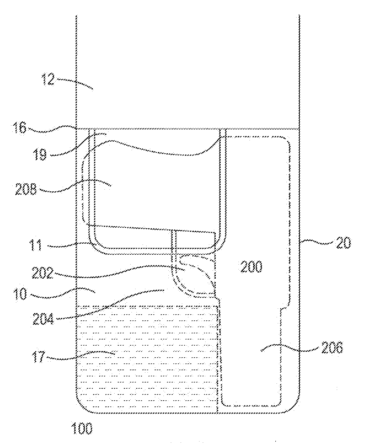
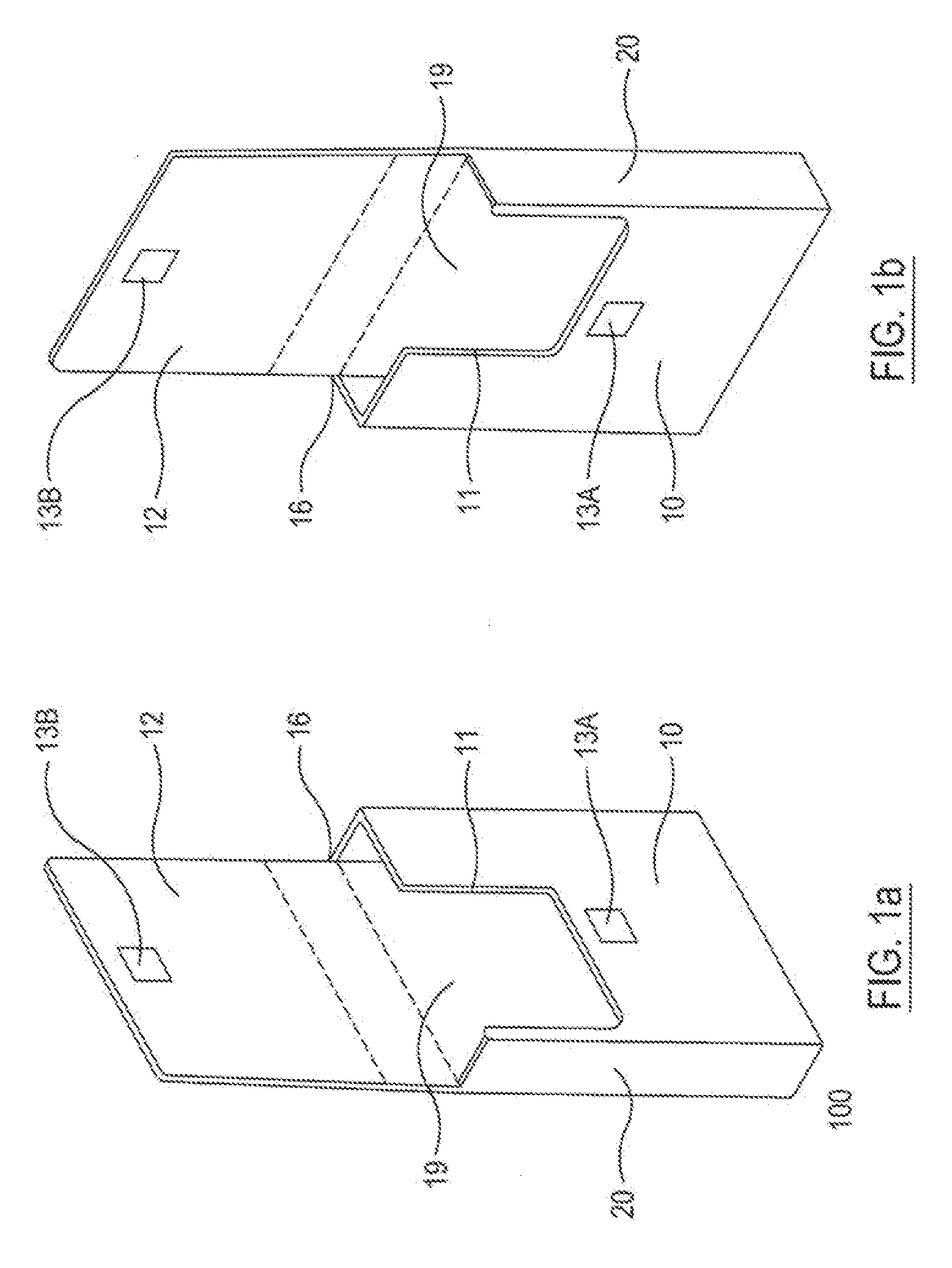
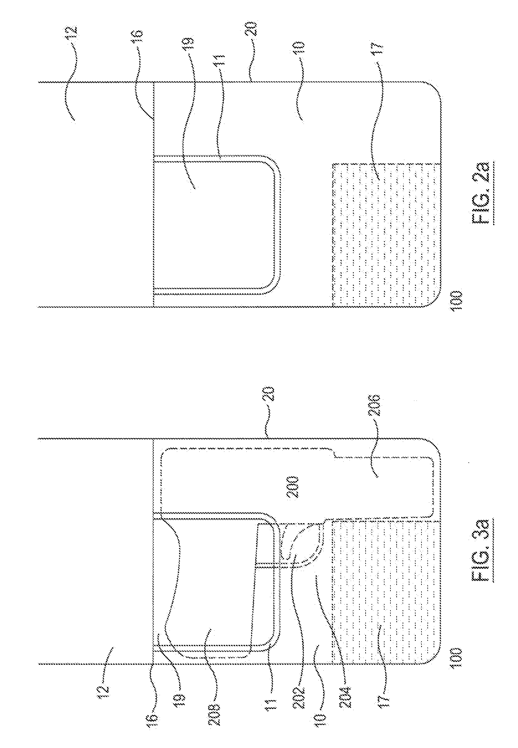
[0032]Referring to FIG. 1A, there is disclosed an isometric view of a right hand embodiment of the carrying device 100 according to the present invention with the cover open. The device is worn on the user's belt or other attachment point. The right hand embodiment may be worn on the user's right side for a conventional draw, or on the user's left side for a cross-draw application. FIG. 1B discloses an isometric view of a left hand embodiment of the carrying device 100 which may be similarly employed in the reverse manner. The carrying device 100 comprises a front face 10, a back face 19, a side panels 20, a bottom panel (not shown in FIG. 1), and a cover 12. The front face 10 with an integrated closure mechanism 13A and a cutout 11 is connected to the back face 19 (not shown in FIG. 1) via two side panels 20, and the bottom panel. The cover 12 with an integrated closure mechanism 13B mating to the closure mechanism 13A is connected to the top edge 16 of the back face 19. In another...


PUM


Abstract

The present invention relates to a concealed firearm carrying device that is configured in such a manner as to alleviate the inherent disadvantages of other concealed carrying devices; it incorporates safety features that good practice dictates without interfering with practical use. The device is made in such a fashion so as to cover the firearm's upper assembly to help retain the shape of the holster and secure the firearm, and to cover the trigger and trigger guard thus reducing the possibility of an accidental discharge when drawing the firearm.The device is further configured to provide sufficient clearance for inserting the fingers of the drawing hand on the front side of the firearm's butt below the firearm's trigger guard. The quick releasing type of closure mechanism including magnetic closure further provides quick withdrawal of the firearm carried within the device and the device is adapted to receive firearms of various sizes.

Description

BACKGROUND OF THE INVENTION[0001]1. Field of the Invention[0002]The present invention generally relates to an improved device for carrying a concealed firearm. More particularly, the present invention relates to a concealed firearm carrying device that is configured in such a manner as to alleviate the inherent disadvantages of other concealed carrying devices available for this purpose; it incorporates safety features that good practice dictates without interfering with practical use.[0003]2. Description of Related Art[0004]Previous concealed carry holsters, cases, or retention devices suffer from one or more of the following disadvantages in use.[0005]Holsters, cases, or retention devices that reveal the shape or part of the weapon are required to be concealed from public view. This is generally accomplished by apparel that must be worn at all times, thus limiting the user's choice of dress or comfort. Some require placement inside or underneath apparel that must be removed or dis...

Claims


Application Information

Patent Timeline
IPC IPC(8): F41C33/00
CPCF41C33/0218
Inventor BAXLEY, CHARLES CLYDE
Owner BAXLEY CHARLES CLYDE
Learn More