Cylinder-type sander

A sanding machine, cylinder type technology, applied in the field of sheet metal processing, to achieve the effect of not easy to deviate, real-time adjustment of settings, and large floating stroke

Inactive Publication Date: 2009-10-28
JIANGSU HUANLI TECH DEV CO LTD
View PDF0 Cites 5 Cited by
  • Summary
  • Abstract
  • Description
  • Claims
  • Application Information

AI Technical Summary

Problems solved by technology

Market research shows that this problem is common, ranging from about one year to...

Method used


Image

  • Cylinder-type sander
  • Cylinder-type sander

Examples


Embodiment Construction

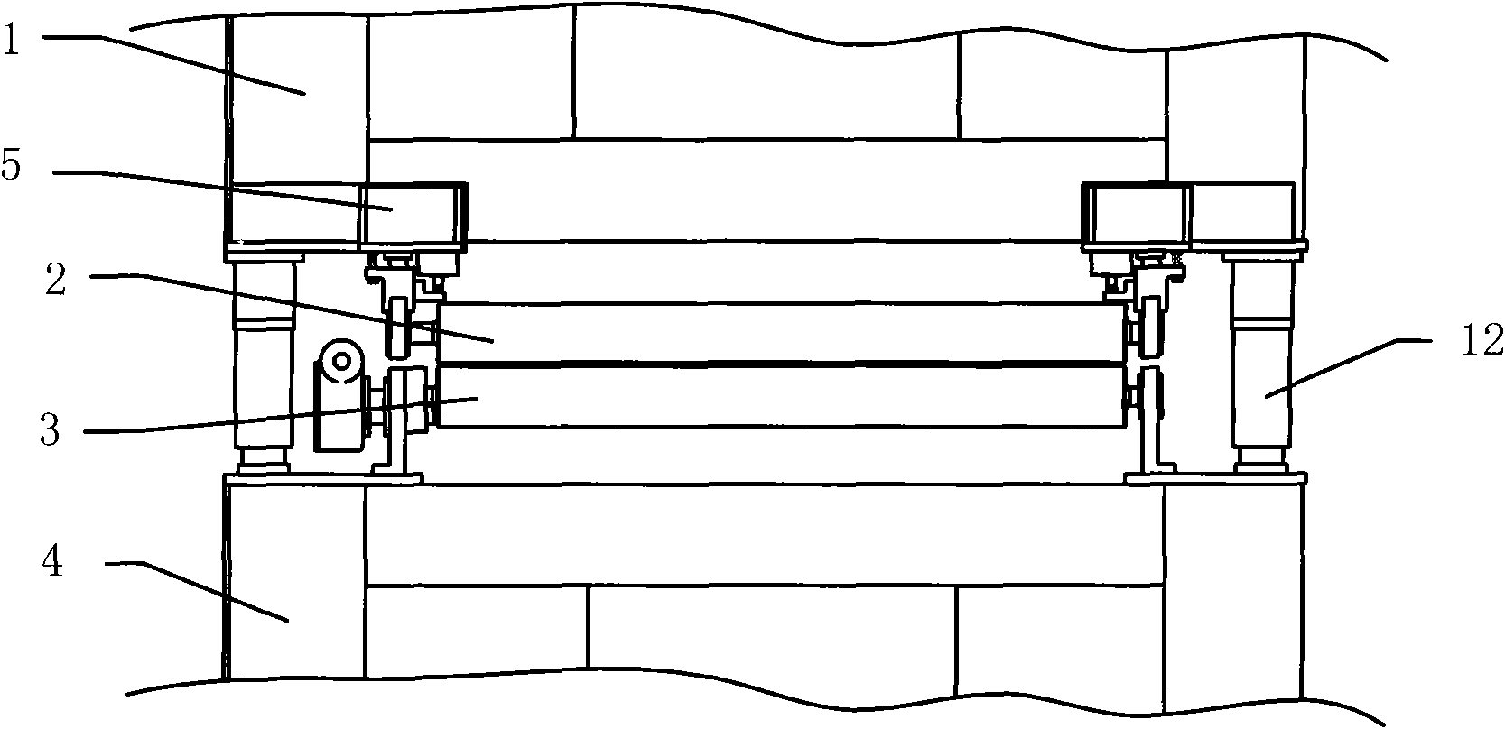
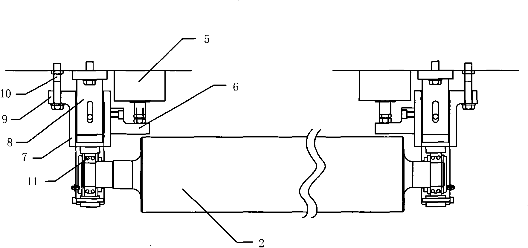
[0023] Such as figure 1 , figure 2 The cylinder sander shown includes an upper frame 1, an upper pressure roller 2, a lower cover rubber roller 3, and a lower frame 4. The lower end of the upper frame 1 is provided with an upper pressure roller 2, and the lower frame 4 is The lower cover rubber roller 3 is installed at the position where the end face faces the upper pressing roller 2. The special feature is that a floating pressing mechanism is installed between the upper frame 1 and the upper pressing roller 2, which includes a cylinder 5. Guiding device and adjusting device, the fixed end of the cylinder 5 is connected to the upper frame 1, the piston head of the cylinder 5 is floatingly connected to the guiding device, the guiding device is connected to the upper pressing roller 2, and the connection between the guiding device and the upper pressing roller 2 is installed with Adjusting device, it is the self-aligning ball bearing 11, and the self-aligning ball in it is co...


PUM


Abstract

The invention relates to a cylinder-type sander, which belongs to the technical field of board processing. The sander comprises an upper rack, an upper press roller, a lower rubber-covered roller and a lower rack, wherein the lower end face of the upper rack is provided with the upper press roller, and a position of the upper end face of the lower rack, which is just opposite to the upper press roller, is provided with the lower rubber-covered roller. The sander has the characteristics that a floating compaction mechanism is arranged between the upper rack and the upper press roller; the floating compaction mechanism comprises a cylinder, a guiding device and a regulating device; a fixed end of the cylinder is connected with the upper rack; a piston head of the cylinder is tightly supported against the guiding device; the guiding device is connected with the upper press roller; the connection position of the guiding device and the upper press roller is provided with the regulating device; and a lifting upright post is erected between the upper rack and the lower rack. The sander can quantitatively adjusts the compaction force of the upper press roller in real time; the upper rack cannot be pushed up because of too high cylinder pressure; in addition, the floating stroke of the upper press roller is enough to bear common boards and cannot damage equipment.

Description

technical field [0001] The invention relates to a sander, in particular to a cylinder type sander, which belongs to the technical field of plate processing. Background technique [0002] At present, the common heavy-duty thickness sanding machines in the domestic market, the pressing force of the upper pressure roller comes from coil springs or disc springs. For the coil spring, the floating range of the upper pressure roller is large, which is beneficial to protect the equipment. [0003] However, the compression force of the coil spring is difficult to adjust and set, and users often can only adjust the pre-compression length of the coil spring based on experience. For plywood, because of the large thickness deviation of the board, there will often be insufficient pressing force in the production site, and the board will stop in the sanding machine. Moreover, once the board stops in the sander, the board will be sanded out of a deep groove and scrapped. [0004] At the ...

Claims


Application Information

Patent Timeline
IPC IPC(8): B24B21/12B24B21/18
Inventor 吴鸣吴佳雯
Owner JIANGSU HUANLI TECH DEV CO LTD
Why Eureka
Try Eureka