
Corner grinding machine tool

A grinding machine and tooling technology, which is applied in the direction of grinding workpiece support, grinding machine parts, grinding feed movement, etc., can solve the problems of low production efficiency, low processing efficiency, and low dimensional accuracy, and achieve convenient control , The effect of high grinding efficiency

Inactive Publication Date: 2019-02-26
NINGBO FOTILE KITCHEN WARE CO LTD
View PDF13 Cites 3 Cited by
  • Summary
  • Abstract
  • Description
  • Claims
  • Application Information

AI Technical Summary

Problems solved by technology

[0002] In modern industry, a large number of metal parts need to be polished and rounded. Usually, these grinding processes are freely operated by workers. One side needs to be polished many times, and only one corner can be polished at a time. The processing efficiency Low, labor intensity is high
In order to process products with high precision and beautiful appearance, there are strict requirements on the grinding size of the corners during grinding. It is necessary to ensure the stability of the grinding feed and the symmetry of the grinding angles on both sides. The corner grinding required by the design requires workers to grind while testing, and there are high requirements for workers' operating skills, the production efficiency is low, and the dimensional accuracy is not high

Method used


Image

  • Corner grinding machine tool
  • Corner grinding machine tool
  • Corner grinding machine tool

Examples


Embodiment Construction

[0022] The present invention will be further described in detail below in conjunction with the accompanying drawings and embodiments.

[0023] Such as Figure 1-8 Shown is a preferred embodiment of the present invention.

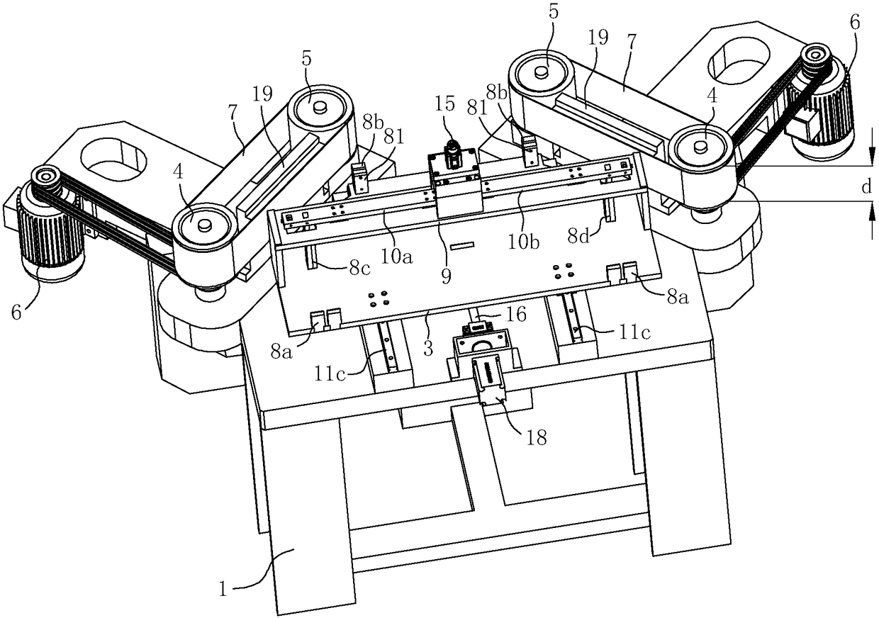
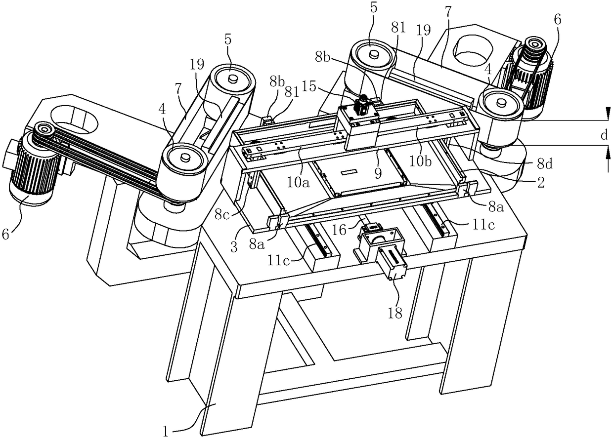
[0024] A corner grinding machine tooling, the workpiece 2 in the tooling is a smoke collecting hood, including

[0025] Rack 1;

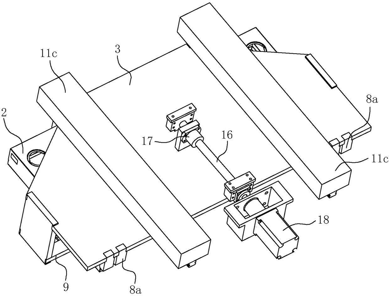
[0026] The platform 3 for placing the workpiece 2 to be polished is located above the table top of the frame 1 and can slide horizontally back and forth. The platform 3 is installed on the table top of the frame 1 through the third guide rail structure 11c. A positioning structure for positioning the workpiece 2 to be ground on the platform.

[0027] The platform drive mechanism is used to drive the platform 3 to slide back and forth horizontally relative to the frame 1; the platform drive mechanism includes a transmission screw 16, which is supported on the table surface of the frame 1 and can rotate around its own axis. The a...


PUM


Abstract

The invention relates to a corner grinding machine tool. The tool is characterized by comprising a rack, a platform used for placing a to-be-ground workpiece, a platform driving mechanism and two grinding mechanisms, wherein the platform is arranged above the table top of the rack, and the positioning structure used for positioning the to-be-ground workpiece on the platform is arranged on the platform; the platform driving mechanism is used for driving the platform to horizontally slide back and forth; the two grinding mechanisms are arranged on the left side and the right side of the rear part of the rack and correspond to two grinding corners of the to-be-ground workpiece respectively; each grinding mechanism comprises a driving belt wheel and a driven belt wheel, an abrasive belt is obliquely arranged between each driving belt wheel and the corresponding driven belt wheel, and the width of each abrasive belt is larger than the height of the grinding corners of the to-be-ground workpiece. The corner grinding machine tool can be used for grinding the two side corners of the to-be-ground workpiece at the same time, and the tool can precisely grind the workpiece with the corners meeting design requirements. The corner grinding machine tool can be used for automatically grinding the two side corners of the to-be-ground workpiece at the same time, and can precisely grind the workpiece with the corners meeting the design requirements.

Description

technical field [0001] The invention relates to a corner grinding device, in particular to a corner grinder tool suitable for grinding the corners of a smoke collecting hood. Background technique [0002] In modern industry, a large number of metal parts need to be polished and rounded. Usually, these grinding processes are freely operated by workers. One side needs to be polished many times, and only one corner can be polished at a time. The processing efficiency Low, the labor intensity of workers is high. In order to process products with high precision and beautiful appearance, there are strict requirements on the grinding size of the corners during grinding. It is necessary to ensure the stability of the grinding feed and the symmetry of the grinding angles on both sides. The corner grinding required by the design requires workers to grind while testing, and has high requirements for workers' operating skills, low production efficiency, and low dimensional accuracy. T...

Claims


Application Information

Patent Timeline
IPC IPC(8): B24B21/00B24B21/18B24B41/00B24B41/06
CPCB24B21/002B24B21/18B24B41/005B24B41/06
Inventor 叶群李立波茅忠群诸永定
Owner NINGBO FOTILE KITCHEN WARE CO LTD
Learn More