

Internal focus lens
a focus lens and internal technology, applied in the field of compact, large diameter internal focus lenses, can solve the problems of increasing the diameter of the front lens, and reducing the range of viewfinders
- Summary
- Abstract
- Description
- Claims
- Application Information
AI Technical Summary
Benefits of technology
Problems solved by technology
Method used
Image

Examples
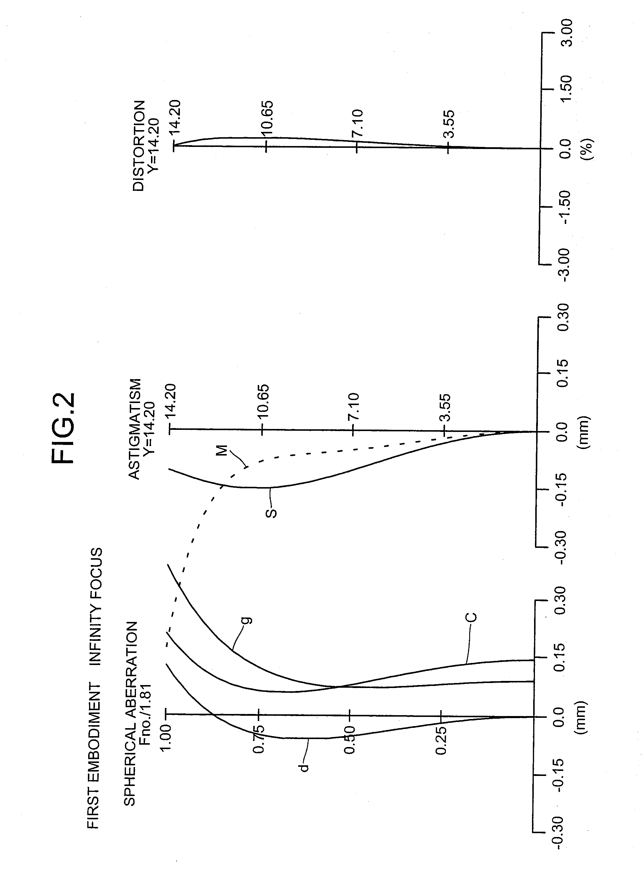
first embodiment
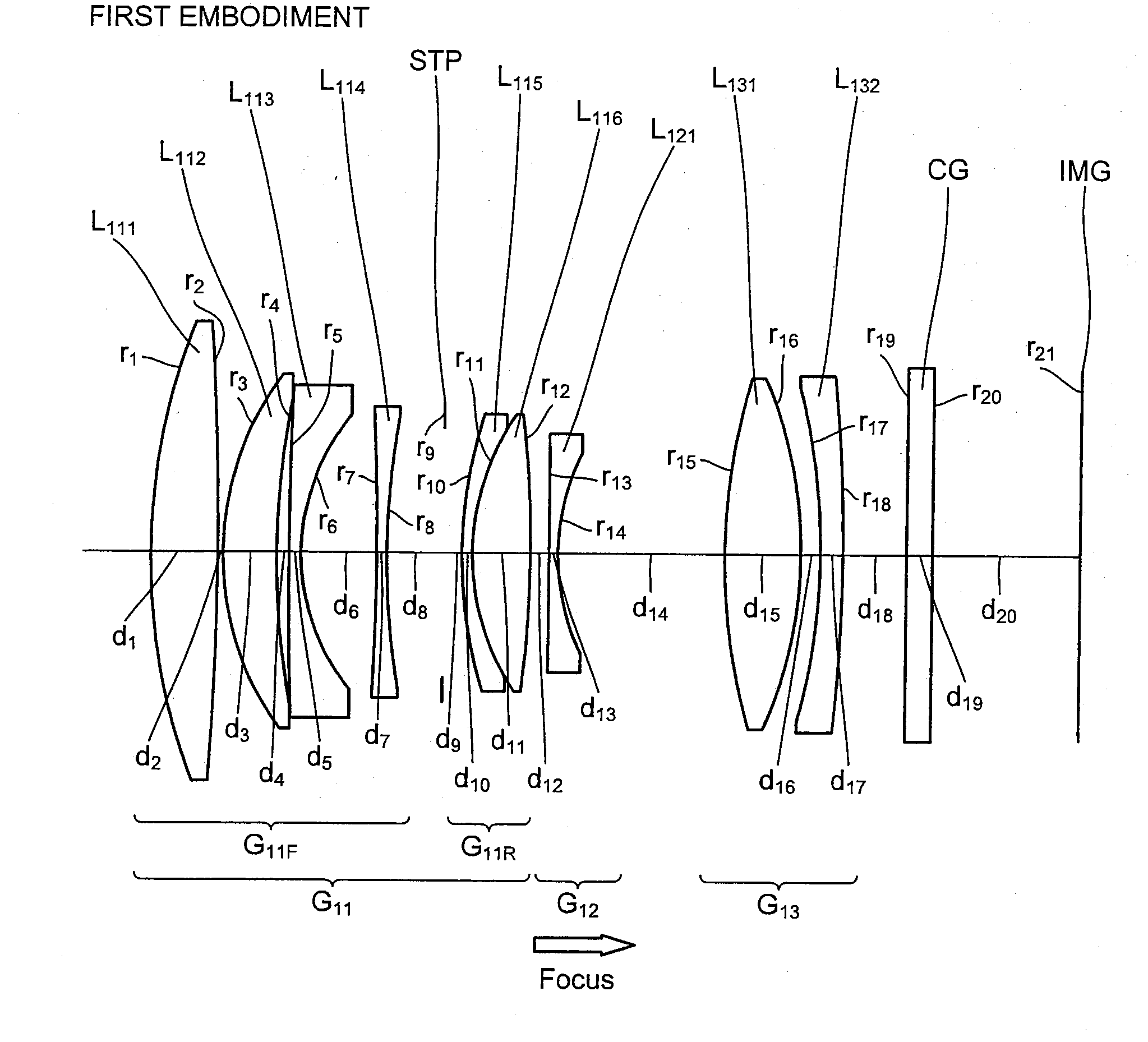
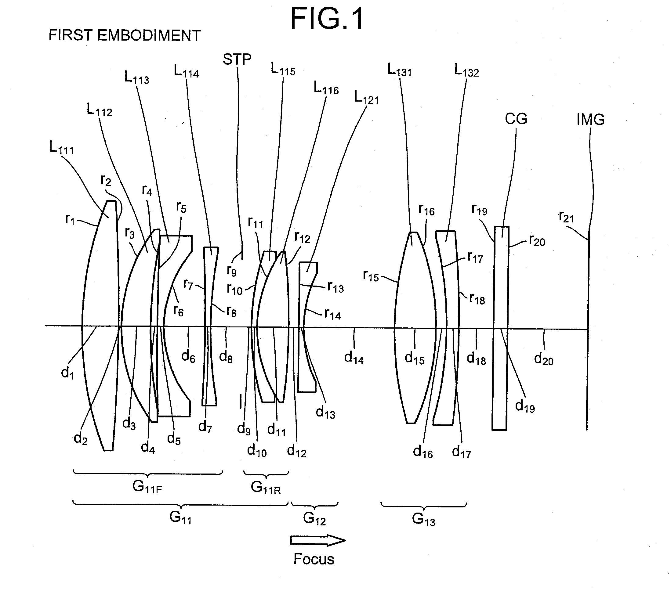
[0067]FIG. 1 is a cross sectional view (along an optical axis) of the internal focus lens according to a The internal focus lens includes sequentially from a side nearest a non-depicted object (object side), a first lens group G11 having a positive refractive power, a second lens group G12 having a negative refractive power, and a third lens group G13 having a positive refractive power. Between the third lens group G13 and an imaging plane IMG, a cover glass CG is disposed. The cover glass CG is disposed as necessary and may be omitted when not necessary. At the imaging plane IMG, the light receiving surface of an imaging sensor such as a CCD, CMOS, etc. is disposed.
[0068]The first lens group G11 includes sequentially from the object side, a front group G11F having a negative refractive power, an aperture stop STP prescribing a given aperture, and a rear group G11R having a positive refractive power. The front group G11F includes sequentially from the object side, a positive lens L...
second embodiment
[0073]FIG. 5 is a cross sectional view (along an optical axis) of the internal focus lens according to a The internal focus lens includes sequentially from the object side, a first lens group G21 having a positive refractive power, a second lens group G22 having a negative refractive power, and a third lens group G23 having a positive refractive power. Between the third lens group G23 and the imaging plane IMG, the cover glass CG is disposed. The cover glass CG is disposed as necessary and may be omitted when not necessary. At the imaging plane IMG, the light receiving surface of an imaging sensor such as a CCD, CMOS, etc. is disposed.
[0074]The first lens group G21 includes sequentially from the object side, a front group G21F having a negative refractive power, the aperture stop STP prescribing a given aperture, and a rear group G21R having a positive refractive power. The front group G21F includes sequentially from the object side, a positive lens L211, a positive lens L212, a ne...
third embodiment
[0079]FIG. 9 is a cross sectional view (along an optical axis) of the internal focus lens according to a The internal focus lens includes sequentially from the object side, a first lens group G31 having a positive refractive power, a second lens group G32 having a negative refractive power, and a third lens group G33 having a positive refractive power. Between the third lens group G33 and the imaging plane IMG, the cover glass CG is disposed. The cover glass CG is disposed as necessary and may be omitted when not necessary. At the imaging plane IMG, the light receiving surface of an imaging sensor such as a CCD, CMOS, etc. is disposed.
[0080]The first lens group G31 includes sequentially from the object side, a front group G31F having a negative refractive power, the aperture stop STP prescribing a given aperture, and a rear group G31R having a positive refractive power. The front group G31F includes sequentially from the object side, a positive lens L311, a positive lens L312, a ne...
PUM
 Abstract
Description
Claims
Application Information