
Self-defense gas spray device

Inactive Publication Date: 2012-11-29
YU SANG UP
View PDF8 Cites 7 Cited by
  • Summary
  • Abstract
  • Description
  • Claims
  • Application Information

AI Technical Summary

Benefits of technology

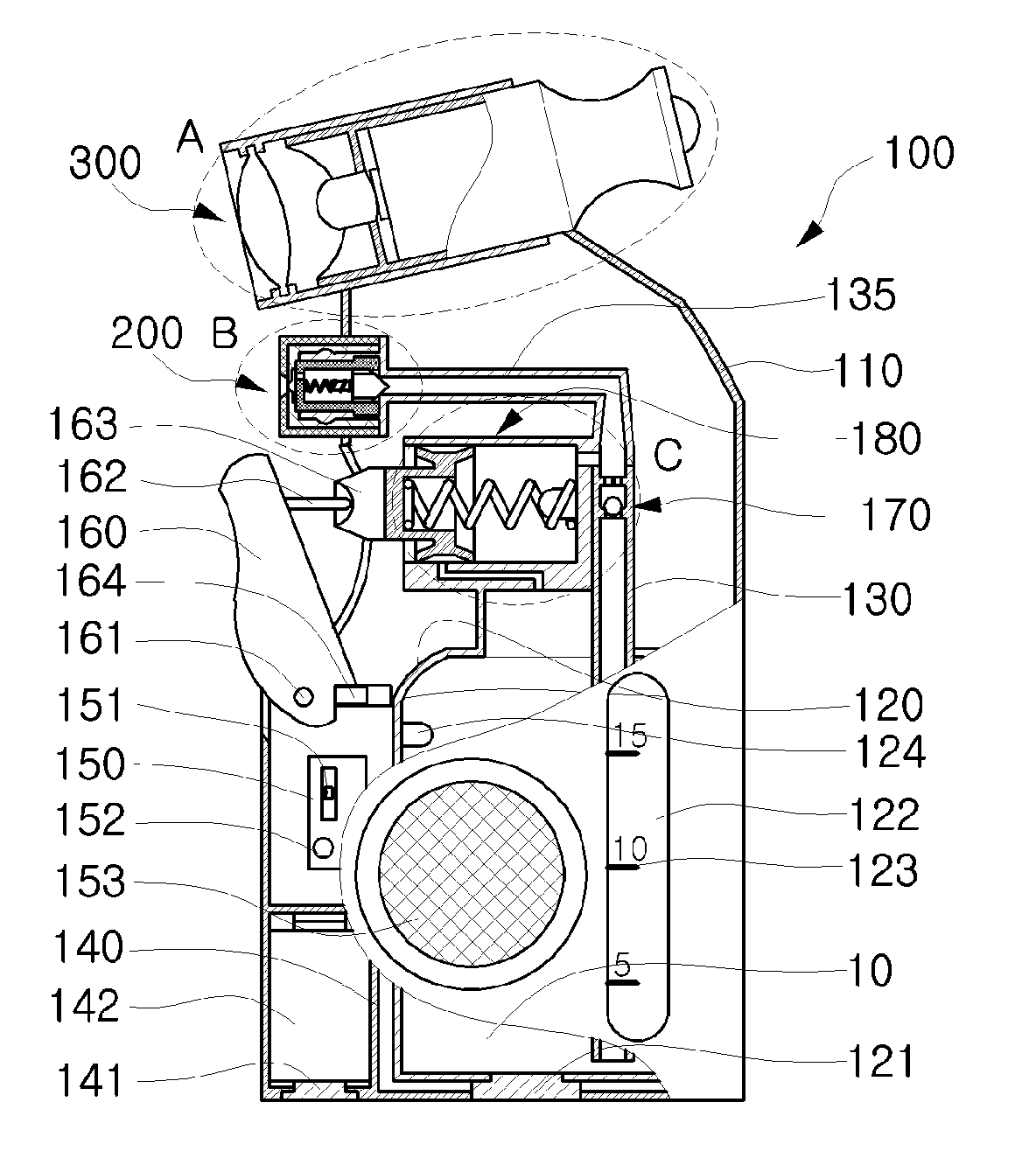
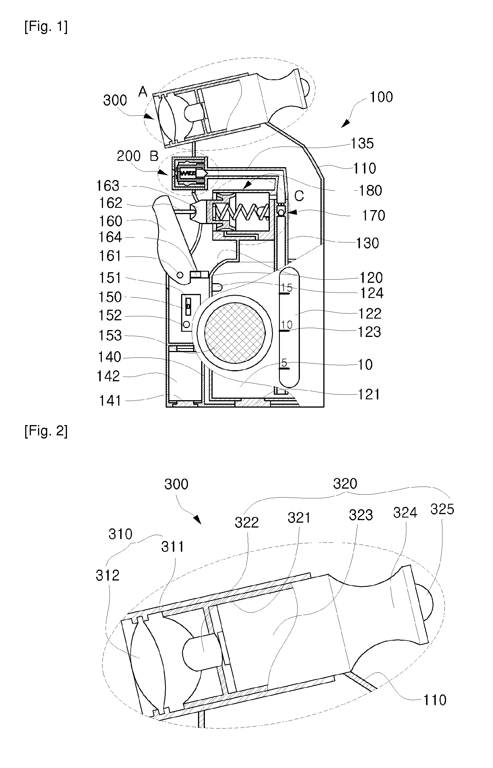
[0012]The self-defense gas spray device according to one aspect of the present invention can concentrate the light, which is emitted from a light emission lamp of the flashlight member, to the target through a focusing lens, and the gas spray member can spray the gas to the target in a state that the light is concentrated onto the target. Thus, the self-defense gas spray device can accurately spray the gas onto a specific part of the target, for example, onto the face of the target, while blinding the eyes of the target in dark environment, such as at night.
[0013]According to another aspect of the present invention, the flashlight member and the gas spray member are inclined with respect to each other by a predetermined angle such that the travelling direction of the light concentrated onto the target from the flashlight member matches with the travelling direction of the gas sprayed from the gas spray member, so the self-defense gas spray device according to another aspect of the present invention can accurately strike the gas to the target in a state that the light is concentrated onto the target.
[0014]According to still another aspect of the present invention

Problems solved by technology

However, according to the conventional self-defense gas spray device, the gas may not readily strike on the target under dark environment, such as at night.
In addition, even if the user sprays the gas to the target after shining a flashlight onto the target under the dark environment, such as at night, the gas may not readily strike on the target.
Further, according to the conventional self-defense gas spray device, the gas is sprayed only in the form of a water stream because there are no other options for the spraying type of the gas, so it may leave many shortcomings when it is necessary to spray gas in other forms rather than the water stream form for the self-defense.
In addition, according to the conventional self-defense gas spray device, the amount of spray gas sources remaining in the conventional self-defense gas spray device may not be recognised from the outside.

Method used


Image

  • Self-defense gas spray device
  • Self-defense gas spray device
  • Self-defense gas spray device

Examples


Embodiment Construction

[0027]Hereinafter, a self-defense gas spray device according to one embodiment of the present invention will be described in detail with reference to accompanying drawings.

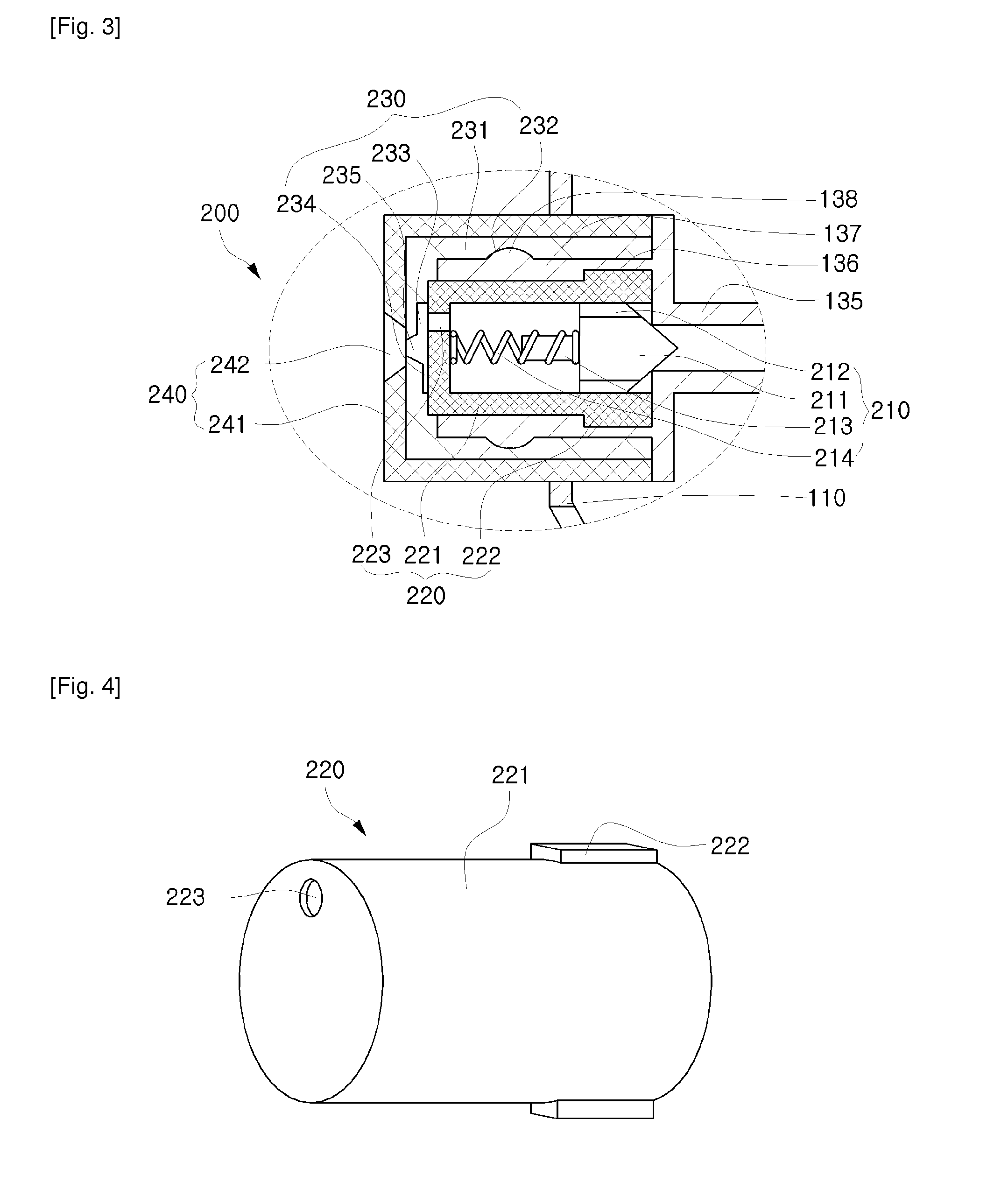
[0028]FIG. 1 is a sectional view showing the structure of a self-defense gas spray device according to one embodiment of the present invention, FIG. 2 is an enlarged view of an A portion shown in FIG. 1, FIG. 3 is an enlarged view of a B portion shown in FIG. 1, FIG. 4 is a perspective view snowing an exhaust part of a self-defense gas spray device according to one embodiment of the present invention, FIG. 5 is a perspective view showing a spraying type change part of a self-defense gas spray device according to one embodiment of the present invention, FIG. 6 is an enlarged view of a C portion shown in FIG. 1, FIG. 7 is a perspective view showing an installation state of a vibration detecting sensor constituting a self-defense gas spray device according to one embodiment of the present invention, FIG. 8 is a secti...


PUM


Abstract

Disclosed is a self-defense gas spray device. The self-defense gas spray device sprays gas to a target so as to achieve self-defense goals. The self-defense gas spray device includes a flashlight member that flashes light to the target to which the gas is to be sprayed, while concentrating the light onto the target; and a gas spray member which evaporates a spray gas source contained therein into the gas and sprays the gas to the target while the light is being concentrated onto the target by the flashlight member. The disclosed self-defense gas spray device has advantages of spraying gas accurately onto a specific part of the target, for example, onto the face of the target, while blinding the eyes of the target in dark environment, such as at night.

Description

TECHNICAL FIELD[0001]The present invention relates to a self-defense gas supply device.BACKGROUND ART[0002]A user carries a self-defense gas spray device to spray tear liquid in the form of gas to a target, such as a burglar.[0003]However, according to the conventional self-defense gas spray device, the gas may not readily strike on the target under dark environment, such as at night.[0004]In addition, even if the user sprays the gas to the target after shining a flashlight onto the target under the dark environment, such as at night, the gas may not readily strike on the target.[0005]Further, according to the conventional self-defense gas spray device, the gas is sprayed only in the form of a water stream because there are no other options for the spraying type of the gas, so it may leave many shortcomings when it is necessary to spray gas in other forms rather than the water stream form for the self-defense.[0006]In addition, according to the conventional self-defense gas spray de...

Claims


Application Information

Patent Timeline
IPC IPC(8): B05B1/14F21L4/00B65D83/00
CPCF41H9/10F41B11/80F41H9/04F21V33/00B05B11/1052B05B11/1091
Inventor YU, SANG-UP
Owner YU SANG UP
Learn More