
Object-oriented cable camera system

a camera system and object-oriented technology, applied in the direction of television systems, directions, instruments, etc., can solve the problems of one cable camera being able, and the other being incapable of non-stop action sports, and achieve the effect of greater immersion in sports games

Inactive Publication Date: 2012-11-29
HALE RICHARD THOMAS
View PDF2 Cites 21 Cited by
  • Summary
  • Abstract
  • Description
  • Claims
  • Application Information

AI Technical Summary

Benefits of technology

[0009]The primary object of the invention is to allow for greater immersion in sports games by the viewer by having the cable camera automatically track the ball in play.
[0012]A further object of the invention is to allow for quicker and smoother reactions by the cable cameras than what is possible via human controlled cable cameras.
[0013]Yet another object of the invention is to allow for automatic camera movements to better frame the shot, allow for greater fluidity and stabililty to the shot, and allow for better tracking of the sports ball.

Problems solved by technology

Currently, only one cable camera is able to be on the sports field at a time because multiple cable cameras could get tangled or interfere with each other.
Previously, cable cameras could not handle non-stop action sports.

Method used


Image

  • Object-oriented cable camera system
  • Object-oriented cable camera system
  • Object-oriented cable camera system

Examples


Embodiment Construction

[0024]Detailed descriptions of the preferred embodiment are provided herein. It is to be understood, however, that the present invention may be embodied in various forms. Therefore, specific details disclosed herein are not to be interpreted as limiting, but rather as a basis for the claims and as a representative basis for teaching one skilled in the art to employ the present invention in virtually any appropriately detailed system, structure or manner.

[0025]The general purpose of the present invention is to provide a new cable camera system that has many of the advantages of the cable cameras mentioned heretofore and many novel features that result in a new cable camera system which is not anticipated, rendered obvious, suggested, or even implied by any of the prior art for the cable cameras, either alone or in any combination thereof.

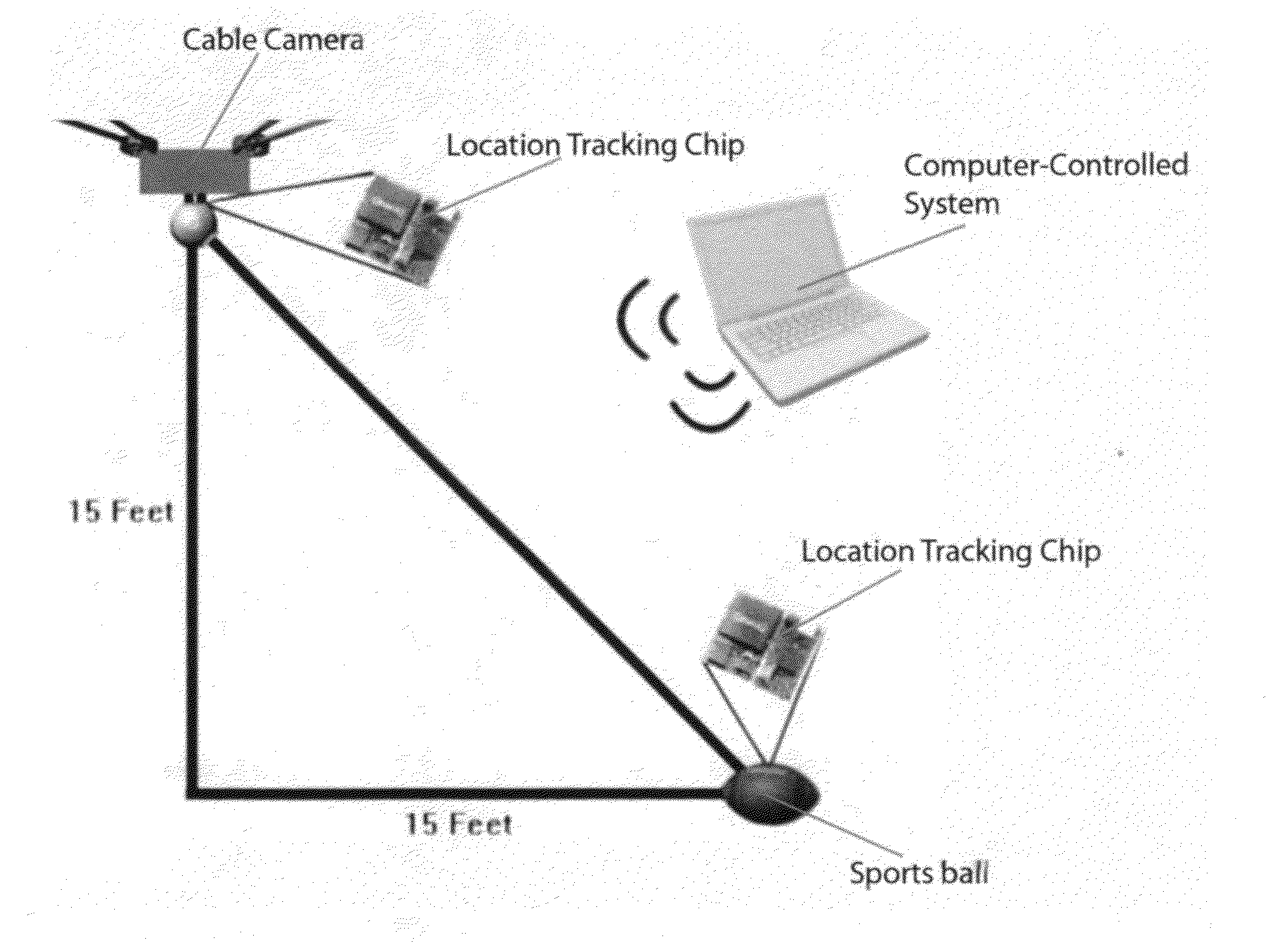
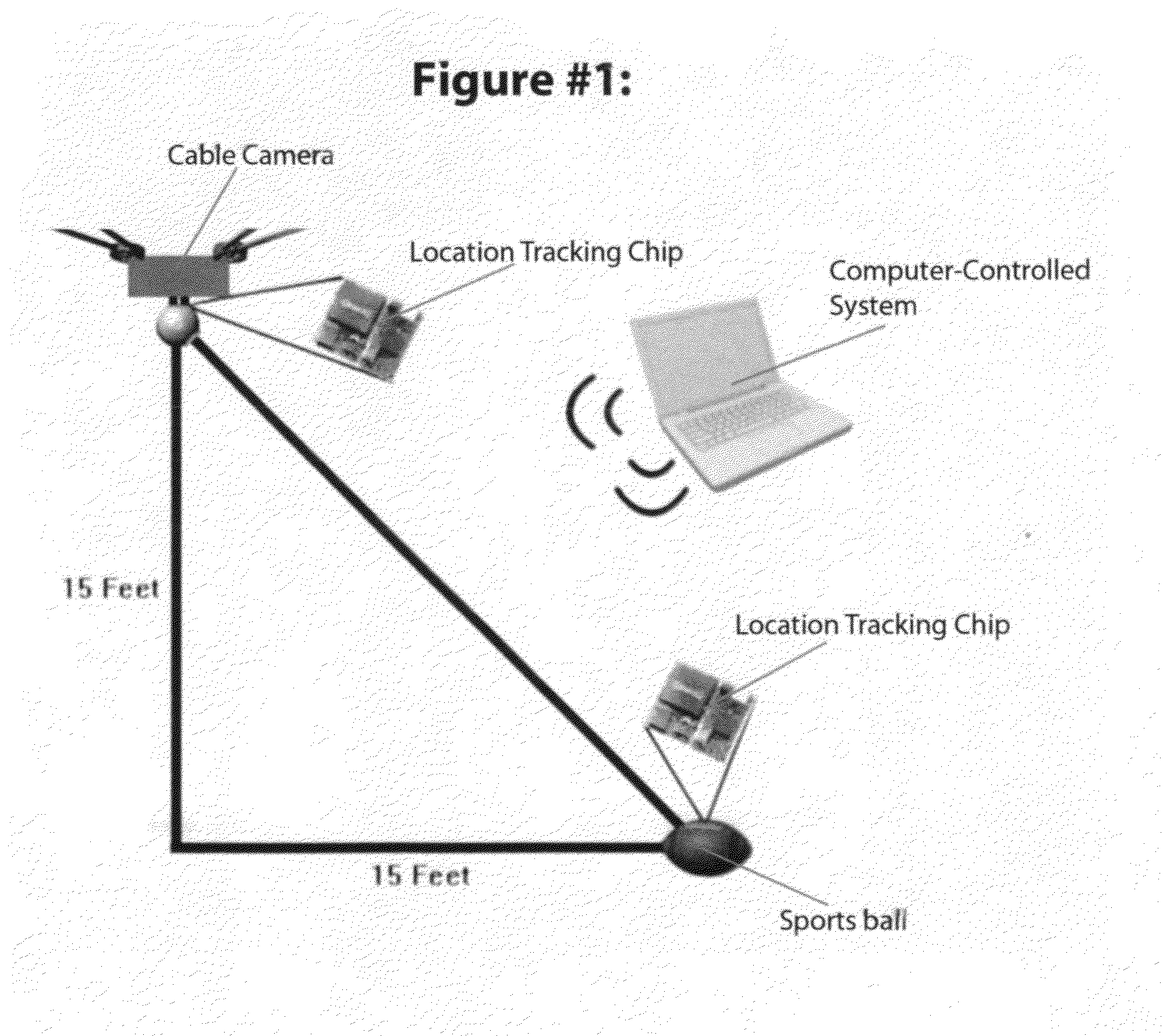
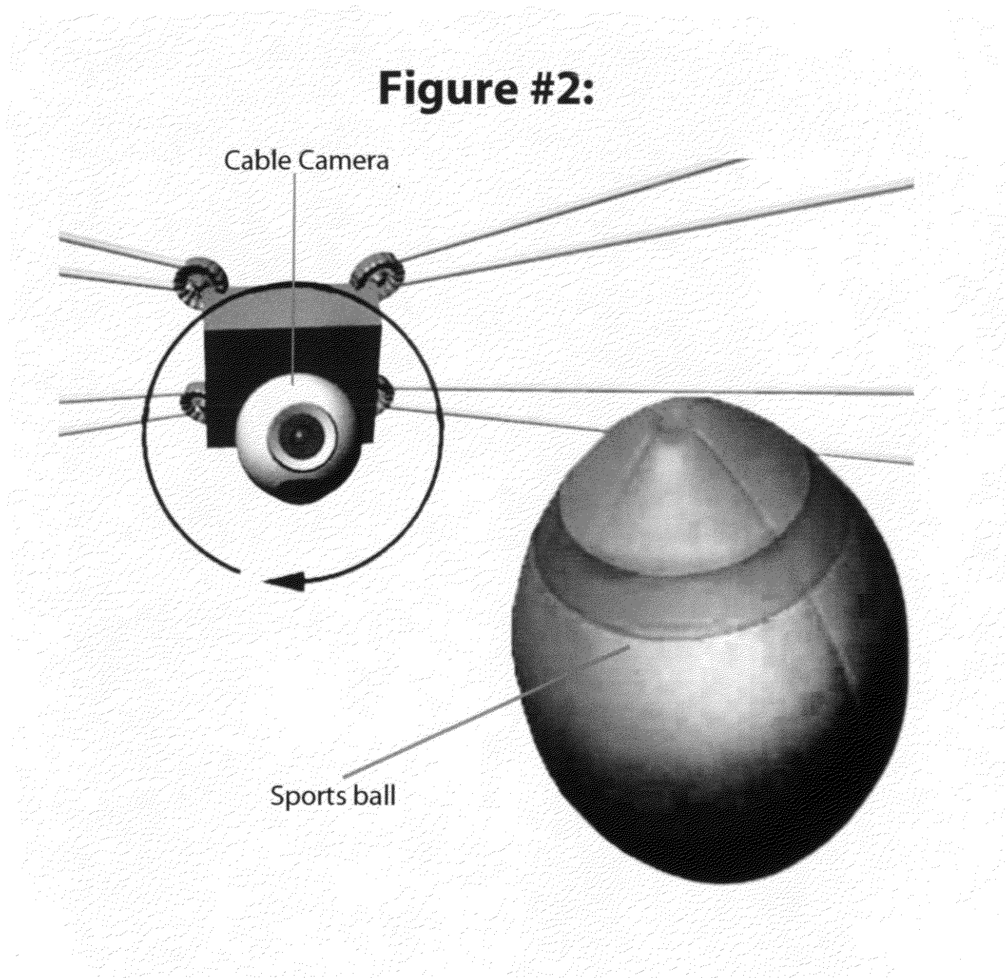
[0026]To attain this, the present invention generally comprises a cable camera system, a sports ball, a computer control system and a tracking chip....


PUM


Abstract

An object-oriented cable camera system that processes the sports ball's position and automatically follows the ball in play in lock step to the sports ball in the sporting arena. The invention is comprised of a cable camera, a computer control system controlling the position of the cable camera and the camera's settings, a tracking chip attached to the sports ball, and a sports ball. A tracking chip is attached to the sports ball. The computer control system monitors the position of the sports ball through this tracking chip and automatically adjusts the cable camera's relative position to the sports ball keeping the cable camera in lock step with the sports ball and therefore providing a superior viewing experience. When the sports ball moves, the computer control system recognizes this change of position and automatically moves the cable camera's position to mirror the sports ball's new position.

Description

CROSS REFERENCE TO RELATED APPLICATIONS[0001]This application is based on provisional application Ser. No. 61 / 464,752, filed on Mar. 9, 2011.STATEMENT REGARDING FEDERALLY SPONSORED RESEARCH OR DEVELOPMENT[0002]Not ApplicableDESCRIPTION OF ATTACHED APPENDIX[0003]Not ApplicableBACKGROUND OF THE INVENTION[0004]This invention relates generally to the field of video cameras and more specifically to cable cameras used in the sporting arena.[0005]The cable camera is a computer-controlled, stabilized, cable-suspended camera system. The system is maneuvered through three dimensions in the open space over a playing area of a stadium or arena by computer-controlled cable-drive system. It is responsible for bringing video game-like camera angles to television sports coverage. The original technology was invented by Garrett Brown in 1984. The cable camera has been in limited use since the mid 1980s when the technology was first patented but until the mid 1990s progress was slow due to limitation...

Claims


Application Information

Patent Timeline
Patent Type & Authority Applications(United States)
IPC IPC(8): H04N7/18
CPCH04N5/232G01S3/7864H04N23/695
Inventor HALE, RICHARD THOMAS
Owner HALE RICHARD THOMAS
Learn More