
Image processing apparatus, image processing method, and program

Active Publication Date: 2012-11-29
CANON KK
View PDF18 Cites 41 Cited by
  • Summary
  • Abstract
  • Description
  • Claims
  • Application Information

AI Technical Summary

Benefits of technology

[0006]The present invention is directed to suppressing a blur in a region in focus and improving image quality of a blurred reg

Problems solved by technology

Japanese Patent Application No. 2008-541051 has a problem that an artifact occurs in a boundary between an object and a background in a case where the background is strongly blurred.
The generation of such intermediate viewpoint images, however, has a problem that the region

Method used


Image

  • Image processing apparatus, image processing method, and program
  • Image processing apparatus, image processing method, and program
  • Image processing apparatus, image processing method, and program

Examples


example modifications

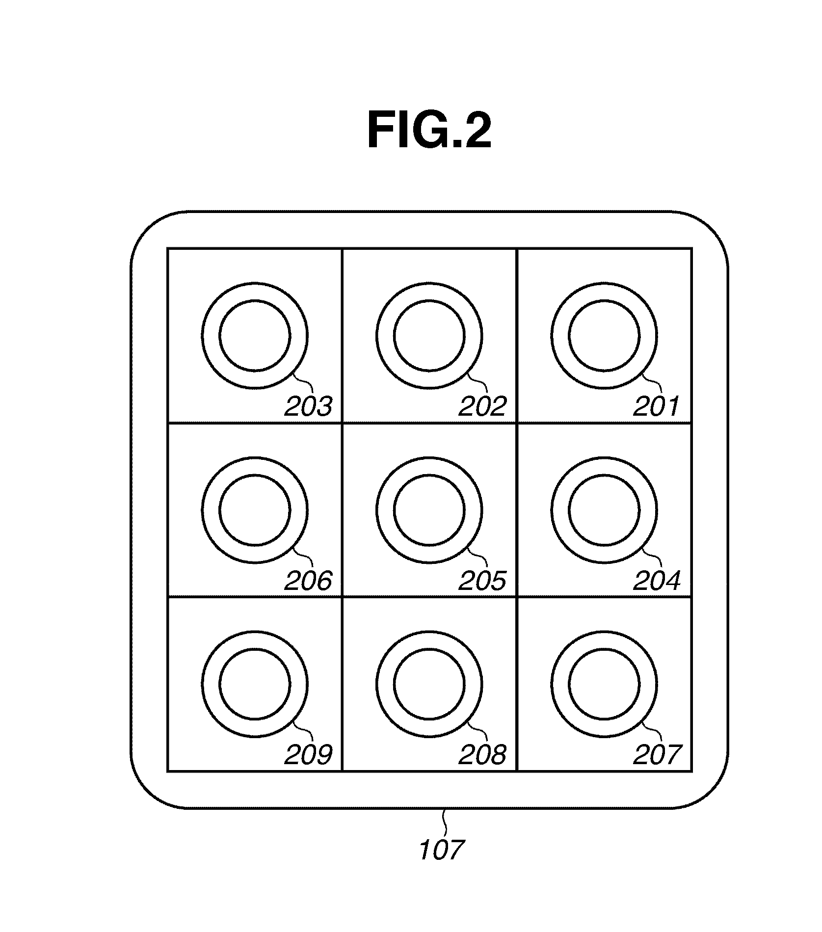
[0085]The present exemplary embodiment has dealt with the case where depth image data 314 is generated by the distance estimation processing in step S404. However, the method of generating depth image data 314 is not limited thereto. For example, a scene depth may be measured by using an external sensor, and depth image data 314 may be generated based on the measurement. The imaging apparatus 107 may include an additional range sensor, and depth image data 314 may be generated based on the range sensor.

[0086]The present exemplary embodiment has dealt with the case where the image synthesis processing unit 306 performs the image synthesis processing on a plurality of pieces of image data in an in-focus region based on the weighting factors Win illustrated in FIG. 12 or 14A, for example. However, the image synthesis processing may be omitted in an in-focus region. For example, image data of an image I15 alone may be used instead. FIG. 14B illustrates weighting factors Win in such a ca...


PUM


Abstract

An image processing device that sets weighting factors for captured image data and interpolation image data region by region based on in-focus state information indicating in-focus states of the respective regions, and synthesizes the captured image data and the interpolation image data based on the weighting factors. A weighting factor for interpolation image data in an in-focus region is smaller than a weighting factor for interpolation image data in at least a part of a region other than the in-focus region.

Description

BACKGROUND OF THE INVENTION[0001]1. Field of the Invention[0002]The present invention relates to a technology for generating a synthesized image based on images captured from a plurality of viewpoints.[0003]2. Description of the Related Art[0004]Techniques for generating an image having a shallow depth of field by applying image processing to captured image data have been discussed heretofore. Japanese Patent Application Laid-Open No. 2011-10194 discusses generating an image having a shallow depth of field by blurring a background region of a scene by filter processing. WO 08 / 050,904 and Uncalibrated Synthetic Aperture for Defocus Control, Computer Vision and Pattern Recognition, 2009. CVPR 2009. IEEE Conference on Date: 20-25 Jun. 2009 (Patent Document 2) discusses deforming a plurality of images having different viewpoints (imaging positions) according to a viewpoint and an object distance for focusing. The deformed images are synthesized to generate a synthesized image having a s...

Claims


Application Information

Patent Timeline
IPC IPC(8): G06K9/40
CPCH04N5/23229H04N5/2258H04N23/45H04N23/80
Inventor NAKADA, YUICHI
Owner CANON KK
Learn More