Floating fastener

Inactive Publication Date: 2012-11-29
HANWIT PRECISION IND LTD
View PDF13 Cites 17 Cited by
  • Summary
  • Abstract
  • Description
  • Claims
  • Application Information

AI Technical Summary

Benefits of technology

[0010]The shank head of the locking shank is forced into the center retaining hole of the retaining member at the second plate member when the longitudinal cut planes and bottom stop flange of the locking shank are respectively kept in alignment with the low inside wall portions and high inside wall portions of the retaining member. After insertion of the shank head of the locking sh

Problems solved by technology

When the second plate member F is pulled by an external force, a shearing force may be produced, causing disconnection of the relatively thicker shank head B22 from the retaining hole F1 of the second plate member F. During

Method used


Image

  • Floating fastener
  • Floating fastener
  • Floating fastener

Examples


Embodiment Construction

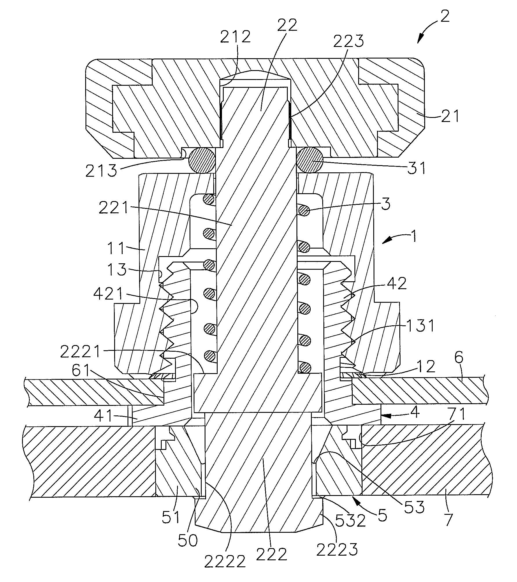
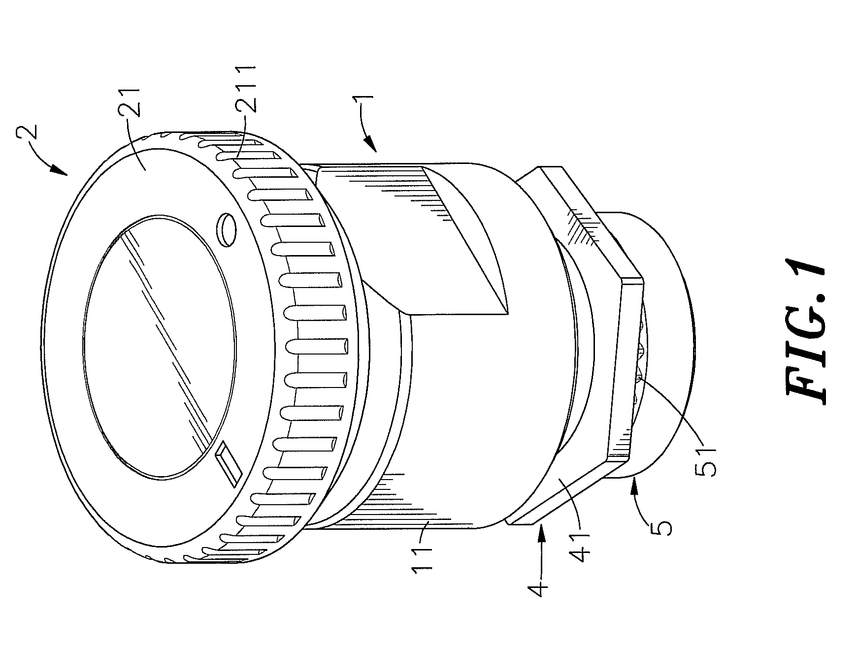
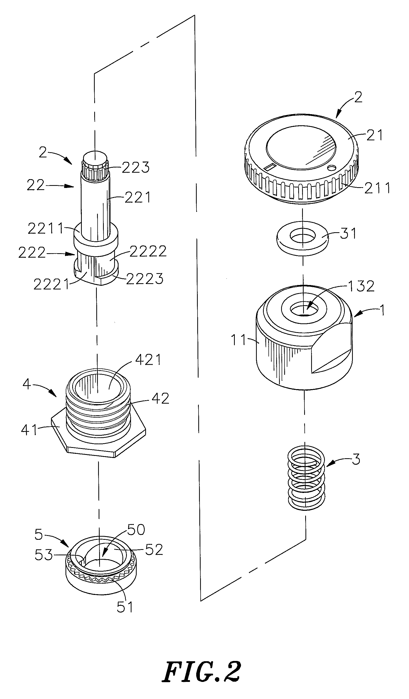
[0021]Referring to FIGS. 1-5, a floating fastener in accordance with a first embodiment of the present invention is shown comprising a connection member 1, a rotary locking device 2, a spring member 3, an elastic cushion ring 31, a lock screw member 4 and a retaining member 5.

[0022]The connection member 1 comprises a tubular body 11 having a bottom open chamber 13, an embossed positioning portion 12 located on the bottom edge thereof around the bottom open side of the bottom open chamber 13, a top center hole 132 located on the top side thereof in communication with the bottom open chamber 13, and an inner thread 131 spirally extending around an inside wall thereof in the bottom open chamber 13.

[0023]The rotary locking device 2 comprises a knob 21 disposed above the connection member 1, and a locking shank 22 connected to the knob 21 and inserted through the top center hole 132 and the bottom open chamber 13 of the connection member 1. The knob 21 has a plurality of vertical tooth g...


PUM


Abstract

A floating fastener includes a connection member fastened to a first plate member with a lock screw member, a retaining member installed in a second plate member, a rotary locking device coupled to the connection member and having a locking shank and a shank head with longitudinal cut planes and insertable through the retaining member, a spring member supported between the top wall of the connection member and a step around the periphery of the locking shank, a knob affixed to the top end of the locking shank and operable to bias the locking shank between a locking position where the shank head is forced into engagement with the retaining member and an unlocking position where the shank head is disengaged from the retaining member, and an elastic cushion ring supported between the connection member and the knob.

Description

[0001]This application claims the priority benefit of Taiwan patent application number 100118141, filed on May 24, 2011.BACKGROUND OF THE INVENTION[0002]1. Field of the Invention[0003]The present invention relates to fasteners for joining metal plate members and more particularly, to a floating fastener, which assures locking stability, avoiding accidental disengagement between parts and accidental separation of the first plate member from the second plate member.[0004]2. Description of the Related Art[0005]Screws or pins are commonly used many different products for the positioning of movable members. For example, a lock pin may be used to lock a sliding box or board member when the sliding rails of the sliding box or board member are moved relative to respective sliding grooves to a predetermined position, facilitating user's operation. In a desk computer system, industrial computer system, work station or any other equipment where movable plate members are detachably arranged tog...

Claims


Application Information

Patent Timeline
IPC IPC(8): F16B39/02
CPCF16B21/02F16B19/109
Inventor CHIU, MING-CHUNG
Owner HANWIT PRECISION IND LTD
Why Eureka
Try Eureka