Apparatus for dispensing hot or boiling water

a technology for hot or boiling water and apparatus, which is applied in the field of apparatus for dispensing hot or boiling water, can solve the problem of no longer being effective in the conditions where it counts, and achieve the effect of durable and reliable protection

Active Publication Date: 2012-12-06
HENRI PETERI BEHEER
View PDF1 Cites 2 Cited by
  • Summary
  • Abstract
  • Description
  • Claims
  • Application Information

AI Technical Summary

Benefits of technology

[0005]An apparatus is envisaged for dispensing hot or boiling water, which has an electric operation with a minimum of parts and which provides a durable and reliable protection against too high an excess pressure in the interior of the reservoir.
[0021]As the valve member is used both for opening the valve in a regular manner when a user is in need of boiling water, and allows for opening of the valve against the action of the closing force in a situation of too high an excess pressure in the reservoir given a particular threshold value, an excess pressure safety provision is provided which is put in motion on a very regular basis. Especially with boiling water, this is an important aspect as boiling water leads to lime scale deposit. Excess pressure safety provisions which are in contact with boiling water and which are not regularly moved run the risk of getting jammed through lime scale deposit, so that they are no longer effective in conditions where it counts, i.e. with an excess pressure prevailing in the reservoir that exceeds a particular threshold value. In hydraulic systems where valves such as, for instance, electromagnetic valves, are used, normally, these valves are included in a pipe system such that, conversely, the pressure that prevails in the upstream pipe part of the electromagnetic valve presses the valve in a closed position. By contrast, with the apparatus according to the present invention, this valve is connected such that the pressure in the upstream pipe part is directed opposite to the dosing force, so that the respective pressure tends to open the valve. It is only owing to the presence of the closing force that in normal conditions the valve remains closed. When a particular threshold value of the excess pressure in the reservoir is exceeded, the valve member is pressed from the closed position. Therefore, the electromagnetic valve has both a function of use, in the sense that with the valve the user controls the dispensing of boiling water, and a function of safety in the sense that with the very same valve, more particularly the same valve body, also an excess pressure safety provision is provided. Therefore, with a minimum of parts, both the operation and an excess pressure safety provision can be realised. An additional advantage is that in case of excess pressure, no steam or water ends up in the sink cupboard in which the apparatus is arranged, but the steam and the water are discharged via the outlet pipe to the sink. As a result, the release of vapour in the sink cupboard is prevented. Since for normal use as well as for the excess pressure safety provision the same valve body is used which is therefore opened and closed on a regular basis, i.e. with each use, the safety provision is reliable and durable.
[0027]Due to the fact that cold water is heavier than hot water, in the downwardly extending part of the pipe water which cools down will collect. Hot water, which, as a result of convection, tends to rise up from the reservoir will therefore rise to the top of the pipe but at that location cannot flow further into the pipe. Thus, boiling water can be prevented from being in continuous contact with the valve, more particularly, the valve member and the valve seat thereof. The valve member part, generally designed to be flexible, which abuts against the valve seat is therefore each time in contact with boiling water only for a very brief time and for the larger part of the remaining time is in contact with water at a much lower temperature. This has a particularly favourable effect on the durability of the valve. Furthermore, as a result of this design of the supply conduit, the heat transfer to the valve body of the valve will be considerably limited. Therefore, via the valve body, only a minimum amount of heat can be given off to the surroundings.

Problems solved by technology

Excess pressure safety provisions which are in contact with boiling water and which are not regularly moved run the risk of getting jammed through lime scale deposit, so that they are no longer effective in conditions where it counts, i.e. with an excess pressure prevailing in the reservoir that exceeds a particular threshold value.

Method used


Image

  • Apparatus for dispensing hot or boiling water
  • Apparatus for dispensing hot or boiling water
  • Apparatus for dispensing hot or boiling water

Examples


Embodiment Construction

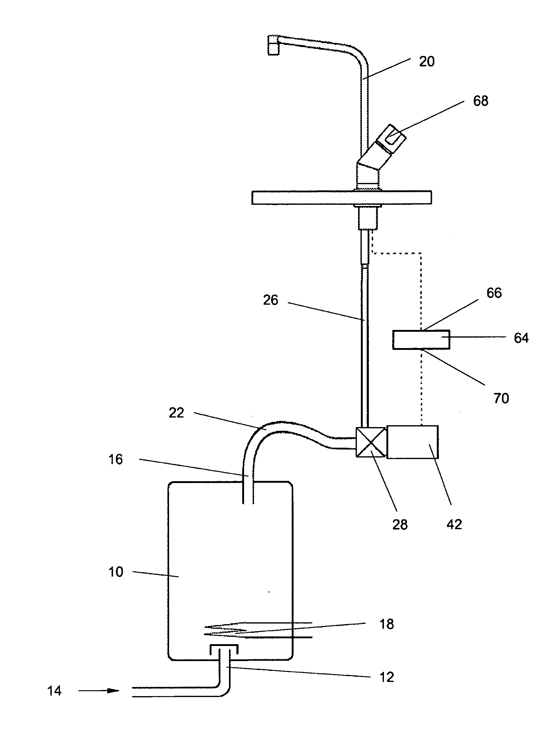
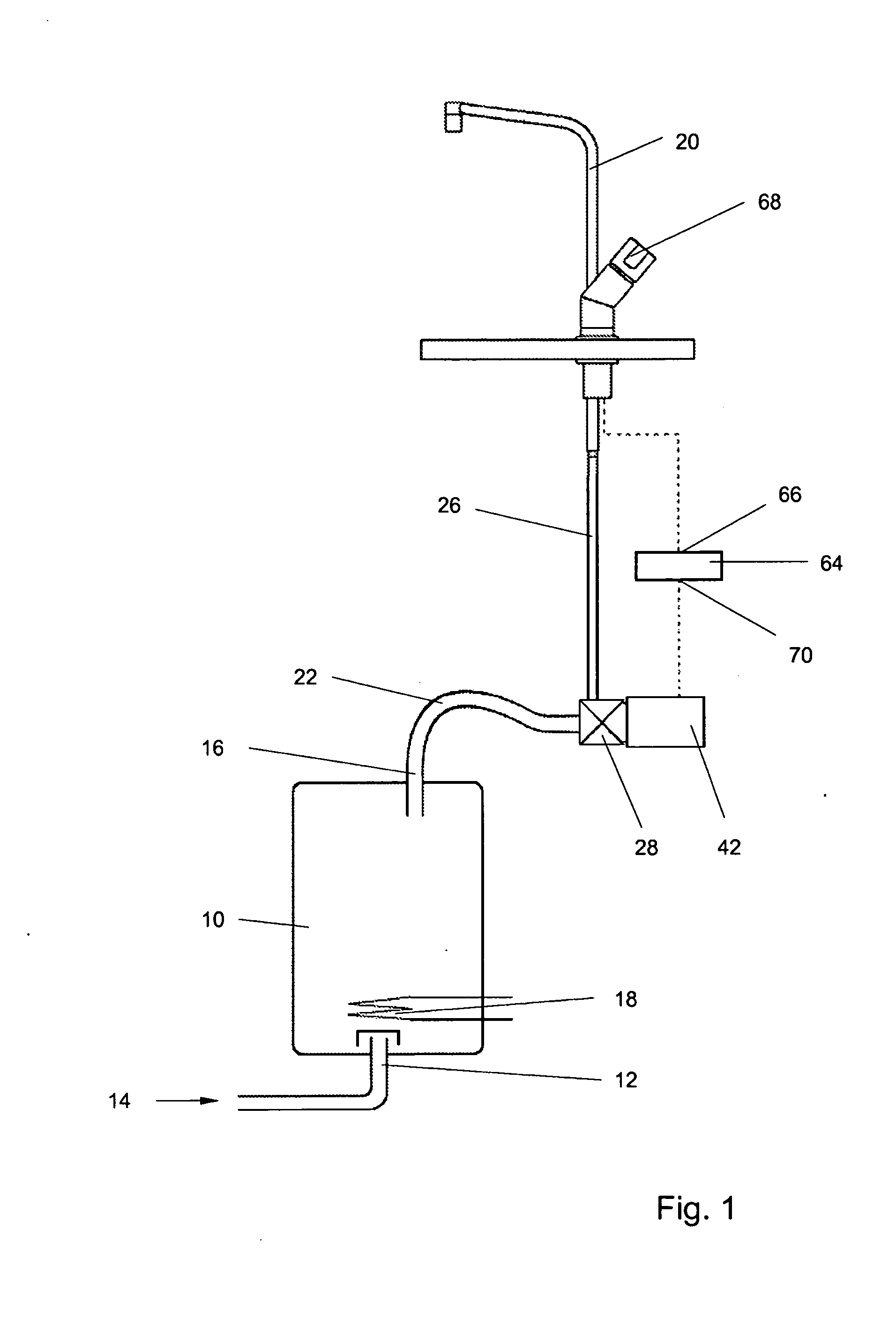
[0033]The exemplary embodiments schematically shown in the Figures serve only as example and serve only for further elucidation. The exemplary embodiment comprises a thermally insulated reservoir 10 which is resistant to an excess pressure prevailing in the interior of the reservoir 10. The reservoir 10 is provided with a supply conduit 12 adjacent an underside of the reservoir 10. The supply conduit 12 is designed for connection to the public water supply system 14. In use, cold tap water is supplied via the supply conduit 12 from the . public water supply system to the reservoir 10 as soon as hot or boiling water is discharged from the reservoir 10. The reservoir 10 is further provided with a discharge conduit 16 adjacent a top side of the reservoir 10. Via the discharge conduit 16, in use, hot or boiling water can be discharged from the reservoir 10. In the reservoir 10, an electric heating element 18 is arranged. Through a suitable control of the electric heating element 18, the...


PUM


Abstract

An apparatus for dispensing hot or boiling water which is provided with a thermally insulated reservoir which is resistant to an excess pressure prevailing in the interior, an electric heating element which is arranged in the reservoir, a discharge conduit and a valve which is included in a fluid communication between the reservoir and the discharge conduit and provided with a valve seat and a movably arranged valve member which in a closed position is pressed with a closing force against the valve seat and which can be brought with an operating element to an opened position, wherein the configuration of the valve and the connection thereof to the fluid communication are such that an excess pressure prevailing in the reservoir exerts a force on the valve body which is directed opposite to the closing force, wherein the closing force is such that the valve member is pressed from the closed position when an excess pressure prevailing in the reservoir reaches a threshold value.

Description

FIELD OF THE INVENTION[0001]The invention relates to an apparatus for dispensing hot or boiling water.BACKGROUND[0002]Such an apparatus was first described in NL-A-7112368, whose British equivalent has number GB-A-1373990. A further development of this apparatus is described in EP-B-0 467 480. The apparatus described in that specification is provided with a thermally insulated reservoir which is resistant to an excess pressure prevailing in the interior of the reservoir. The reservoir is provided with a supply conduit adjacent an underside of the reservoir which is designed for connection to the public water supply system, while in use, cold tap water is supplied from the public water supply system via the supply conduit to the reservoir, as soon as hot or boiling water is discharged from the reservoir. The reservoir further has a discharge conduit adjacent a top side of the reservoir via which discharge conduit, in use, hot or boiling water can be discharged from the reservoir. In ...

Claims


Application Information

Patent Timeline
Patent Type & Authority Applications(United States)
IPC IPC(8): F16L53/00
CPCE03C1/0411F24H9/126Y10T137/6416F24H9/136F24D3/10F24D19/00F24H9/2007
Inventor PETERI, NIELS THEODOOR
Owner HENRI PETERI BEHEER
Why Eureka
Try Eureka