
Safety carabiner

a carabiner and safety technology, applied in the field of safety carabiners, can solve the problems of difficult opening of the carabiner, awkward handling of the carabiner, and often catching on the handling member

Active Publication Date: 2012-12-20
R L WICHARD
View PDF17 Cites 8 Cited by
  • Summary
  • Abstract
  • Description
  • Claims
  • Application Information

AI Technical Summary

Benefits of technology

[0012]The technical problem at the base of the invention therefore consists of providing a carabiner that has a simple and cost-effective structure, and that allows fast and easy opening of the carabiner.
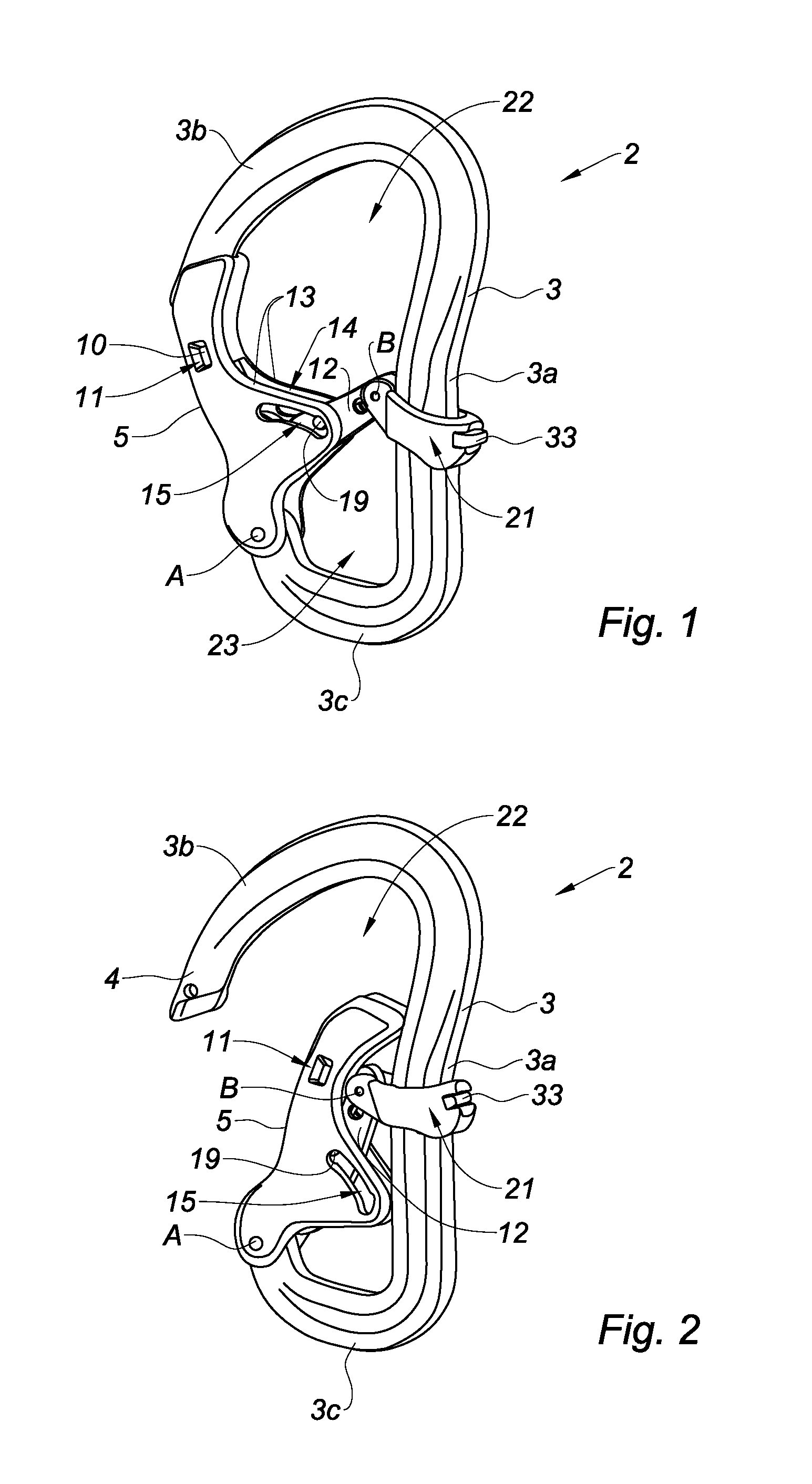
[0019]Arranging the handling member on the body of the carabiner opposite the closing finger allows a user to open the carabiner using one hand, by simply moving the handling member toward the second position thereof using one finger, such as the thumb, and by moving the closing finger toward the open position thereof using another finger, such as the index finger. This thereby results in quick, easy and ergonomic opening of the carabiner.
[0030]Advantageously, the actuating and handling members are configured to separate the first and second basic frames, and the actuating member is removably mounted on the handling member so that in the mounted position, the actuating and handling members separate the first and second basic frames, and such that in the disassembled position, the actuating and handling members allow communication between the first and second basic frames. These measures make it possible to remove a tether received in the second basic frame outside the carabiner, after disassembling the handling and articulation members and moving the closing finger toward the open position thereof.

Problems solved by technology

Such a carabiner has several drawbacks resulting more particularly from the position of the handling member on the closing finger.
In fact, when a user seeks to remove the rope or strap positioned inside the carabiner, the latter often catches on the handling member.
Furthermore, such a position of the handling member makes it difficult to open the carabiner, since it is necessary to successively exert pressure on the handling member in a first direction so as to move the latter toward the second position thereof, and pressure on the closing finger in a second direction transverse to the first direction so as to move the closing finger toward the open position thereof.
Such handling of the carabiner is awkward, particularly when it must be done with one hand or by a small user.
Moreover, such a position of the handling member can cause a risk of untimely unlocking of the closing finger, therefore a risk of opening thereof, for example when the handling member rubs against an outside element, such as part of the anchor or a rope.

Method used


Image

  • Safety carabiner
  • Safety carabiner
  • Safety carabiner

Examples


Embodiment Construction

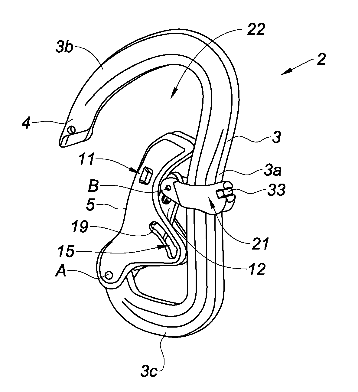
[0066]FIGS. 1 to 14 show a safety carabiner 2 that can be used, inter alia, for climbing, speleology, and water sports, such as sailing, or as a safety measure protecting people working at heights from falling.

[0067]The safety carabiner 2 comprises a generally C-shaped body 3. The body 3 comprises a substantially rectilinear central portion 3a extended at its ends by a first hook-shaped branch 3b and a second curved branch 3c. The first hook-shaped branch 3b comprises a retaining portion 4 at its free end.

[0068]The safety carabiner 2 also comprises a closing finger 5 pivotably mounted around a hinge pin A situated at the free end of the second curved branch 3c, between a closed position in which the closing finger 5 cooperates with the retaining portion 4 of the first hook-shaped branch 3b and an open position in which the closing finger 5 is tilted toward the inside of the carabiner.

[0069]The safety carabiner 2 also comprises locking means movably mounted on the closing finger 5 be...


PUM


Abstract

The carabiner includes a body delimiting a basic frame, a closing finger pivotably mounted on the body between closed and open positions of the basic frame, locking means movably mounted on the closing finger between locked and unlocked positions of the closing finger, and actuating means arranged to move the locking means between the locked and unlocked positions thereof, where the actuating means include a handling member connected to the locking means and movably mounted on a portion of the carabiner body opposite the closing finger, between a first position in which the locking means are in the locked position and a second position in which the locking means are in the unlocked position, the handling member being arranged so that moving the latter between the first and second positions thereof causes the locking means to move between the locked and unlocked positions thereof.

Description

TECHNICAL FIELD[0001]The present invention relates to a safety carabiner used, inter alia, for climbing, speleology, and water sports, such as sailing, or as a safety measure protecting people working at heights from falling.BRIEF DISCUSSION OR RELATED ART[0002]Document DE 42 37 263 describes a safety carabiner including:[0003]a body delimiting an open loop and including first and second ends,[0004]a closing finger pivotably mounted around a hinge pin situated at the first end of the body, between a closed position in which the closing finger cooperates with the second end of the body so as to close the loop, and an open position in which the closing finger is tilted toward the inside of the carabiner,[0005]locking means movably mounted on the closing finger between a locked position in which the locking means cooperate with the second end of the body of the carabiner so as to lock the closing finger in the closed position thereof, and an unlocked position in which the closing finge...

Claims


Application Information

Patent Timeline
IPC IPC(8): F16B45/02
CPCF16B45/02Y10T24/45361Y10T24/4534F16B45/029F16B45/026F16B45/023
Inventor TARDIF, SEBASTIEN
Owner R L WICHARD
Learn More