Display unit

Active Publication Date: 2013-11-28
CONTINENTAL AUTOMOTIVE GMBH
View PDF1 Cites 0 Cited by
  • Summary
  • Abstract
  • Description
  • Claims
  • Application Information

AI Technical Summary

Benefits of technology

[0022]If the display is a liquid crystal display, the prevention of the formation of spo

Problems solved by technology

To comply with these high demands, it is necessary to respect the tolerances of a long

Method used


Image

  • Display unit
  • Display unit
  • Display unit

Examples


Embodiment Construction

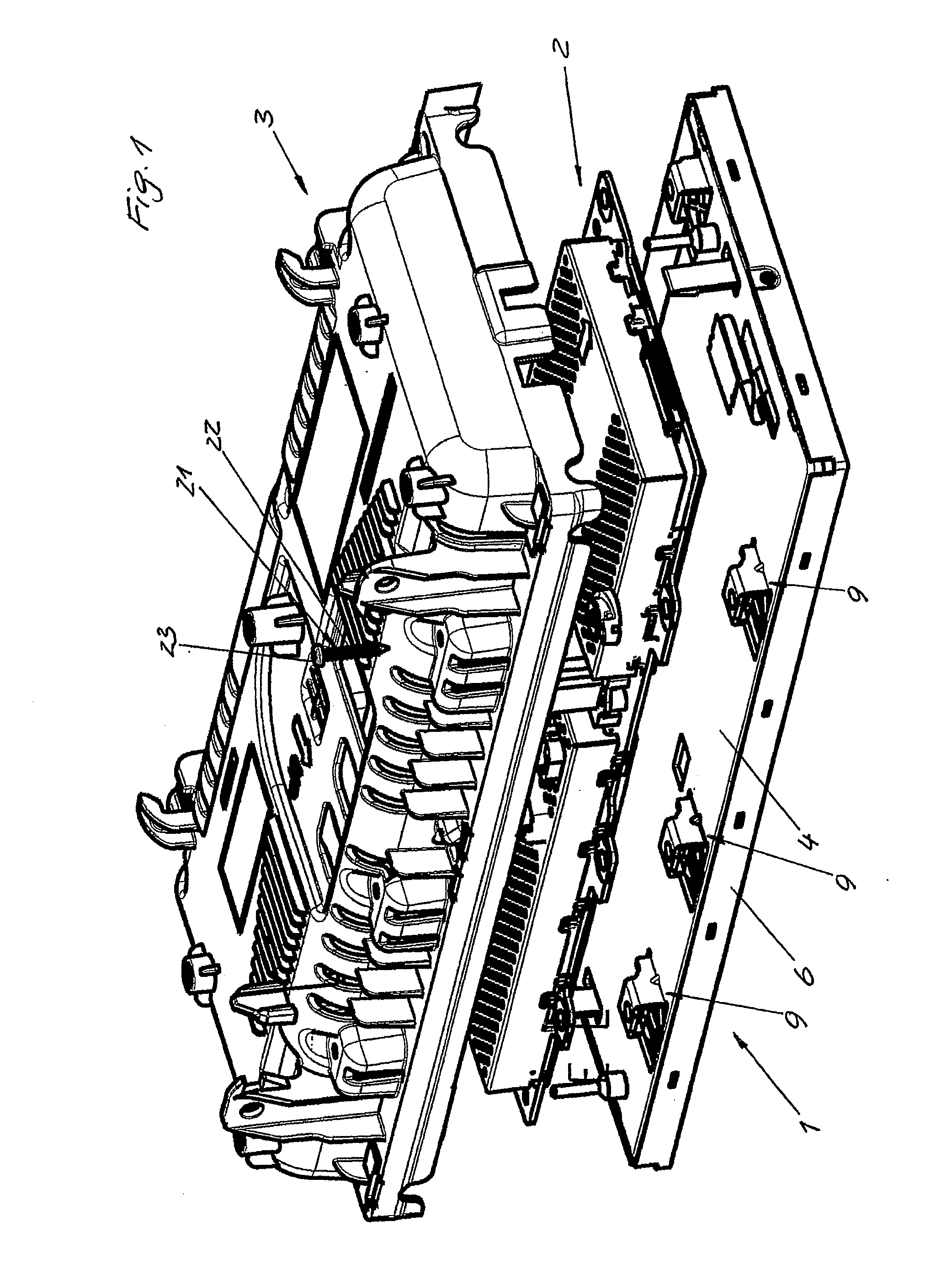
[0029]FIG. 1 is a perspective view of a display unit from the rear side. It has a display rear wall 1, a printed circuit board 2, and a vessel-like housing 3 as a magnesium cast component.

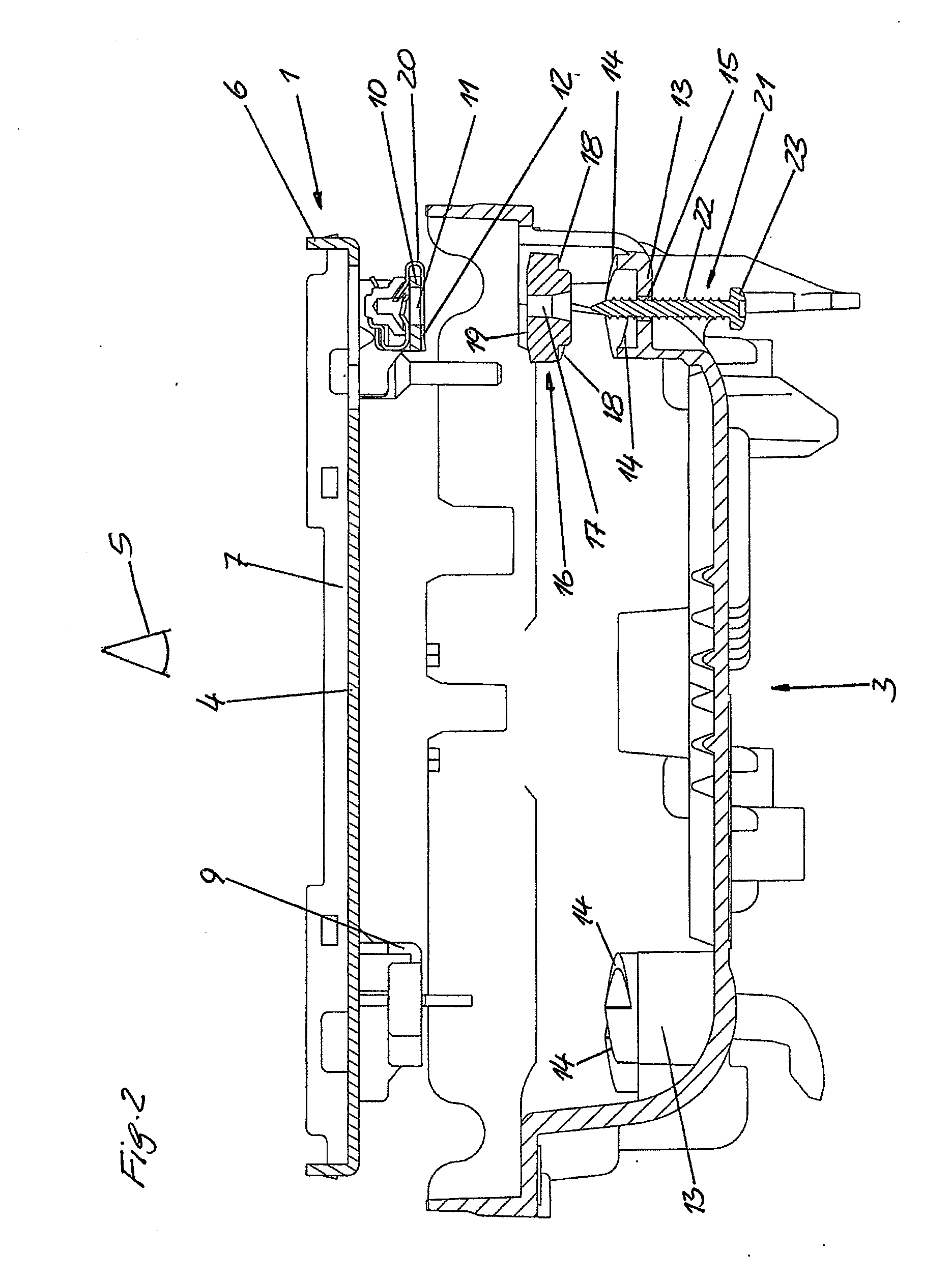
[0030]The display rear wall 1 is a punched bent component comprising a metal sheet and having a base 4 and a peripheral edge 6 that protrudes towards the side of a viewer 5 (FIG. 2).

[0031]In the case-like receiving member 7, which is thereby produced, a liquid crystal display, which is not illustrated, can be inserted (FIG. 2).

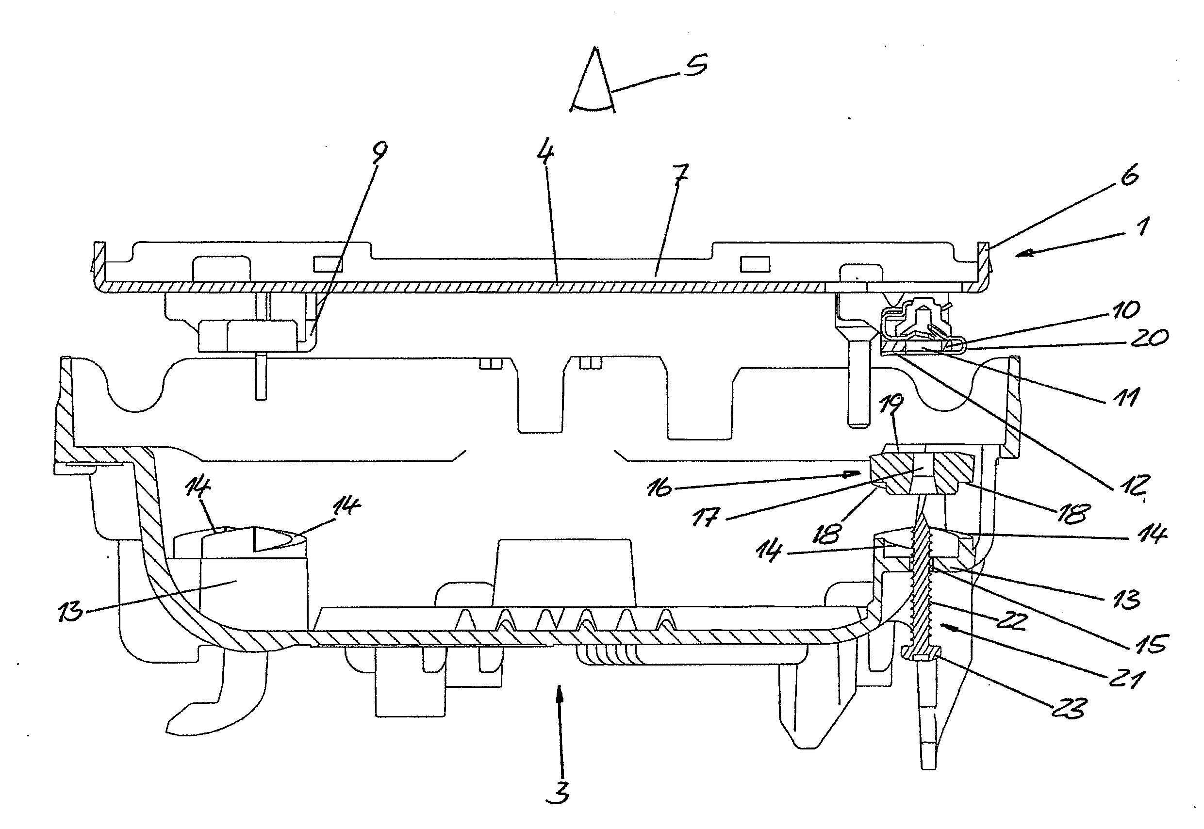
[0032]By punching and bending in the region of the base 4, there are formed along the longitudinal sides of the display rear wall 1 three L-shaped flaps 9, which protrude towards the rear side and have flap portions 10 parallel to the base 4 and which have a through-opening 11.

[0033]The sides of the flap portions 10 facing away from the wall 4 form support faces 12 (FIG. 2).

[0034]Coaxially relative to the through-openings 11, the housing 3 has support domes 13 having support ...


PUM


Abstract

A display unit having a display module, which has a display having a rear display wall with bosses having support surfaces. A housing covers the of the display has support bosses through which fastening screws are guided and can be screwed into holes of the screw bosses to brace the display module against the housing. A spacer is arranged between each screw and support. The surface of the spacer extends parallel to the rear display wall. The spacer is supported on the support boss. The spacer surface and the supporting surface of the support boss rise helically in opposite directions and are concentric to a through-hole. The threaded shaft of the fastening screw protrudes through a spacer through-opening and is frictionally locked to the inner wall of the spacer through-opening to a certain torque.

Description

CROSS-SECTION TO RELATED APPLICATIONS[0001]This is a U.S. national stage of application No. PCT / EP2011 / 073649, filed on 21 Dec. 2011. Priority is claimed on German Application No. 10 2010 055 482.0 filed 22 Dec. 2010, the content of which is incorporated here by reference.BACKGROUND OF THE INVENTION[0002]1. Field of the Invention[0003]The invention relates to a display unit having a display module, which has a display having a display rear wall at the rear side of the display, the display rear wall having a plurality of screw domes that protrude in the direction towards the side facing away from the display and which have support faces parallel with plane of the display rear wall, having a housing that covers the rear side of the display module and support domes opposite the screw domes and which have support faces and through-holes directed towards the screw domes and through which there are inserted securing screws supported with the screw heads thereof at the side facing away fro...

Claims


Application Information

Patent Timeline
IPC IPC(8): G02F1/1333
CPCG02F1/133308G06F1/1601
Inventor KARL, KLAUSKISSEL, ROBERT WOLFGANGLUCK, HANS-JOACHIM
Owner CONTINENTAL AUTOMOTIVE GMBH
Why Eureka
Try Eureka