
Environmental sensor with tensioned wire exhibiting varying transmission characteristics in response to environmental conditions

a technology of environmental sensors and tensioned wires, applied in the field of sensing methods, can solve problems such as diaphragm deflection

Active Publication Date: 2012-12-27
ETEGENT TECH
View PDF5 Cites 26 Cited by
  • Summary
  • Abstract
  • Description
  • Claims
  • Application Information

AI Technical Summary

Benefits of technology

[0006]Embodiments of the invention are generally directed to a sensor and a sensing method, in which signals communicated over one or more w

Problems solved by technology

For example, pressure of the environment in which the sensor is positioned may cause the diaphragm to deflect.

Method used


Image

  • Environmental sensor with tensioned wire exhibiting varying transmission characteristics in response to environmental conditions
  • Environmental sensor with tensioned wire exhibiting varying transmission characteristics in response to environmental conditions
  • Environmental sensor with tensioned wire exhibiting varying transmission characteristics in response to environmental conditions

Examples


Embodiment Construction

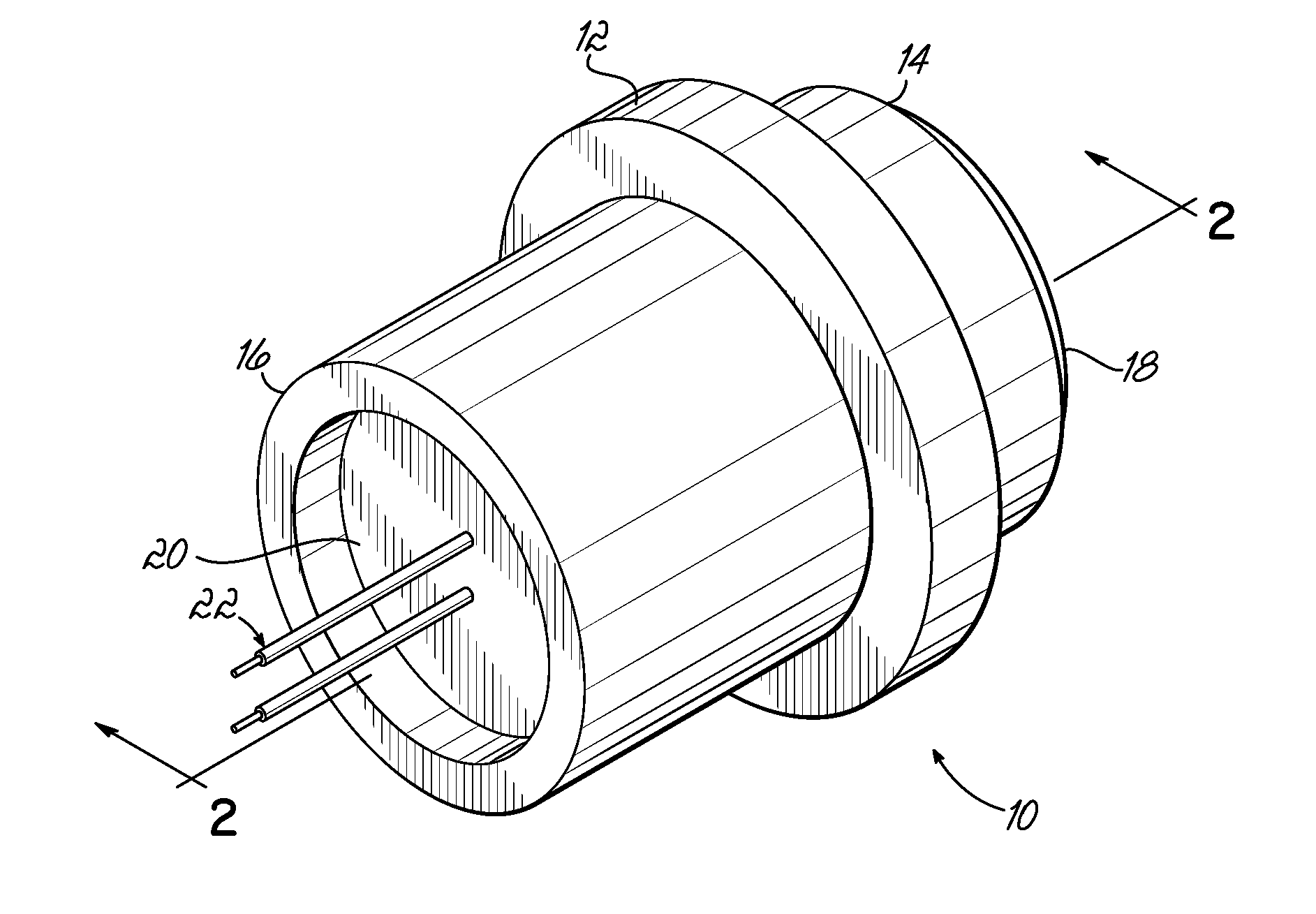
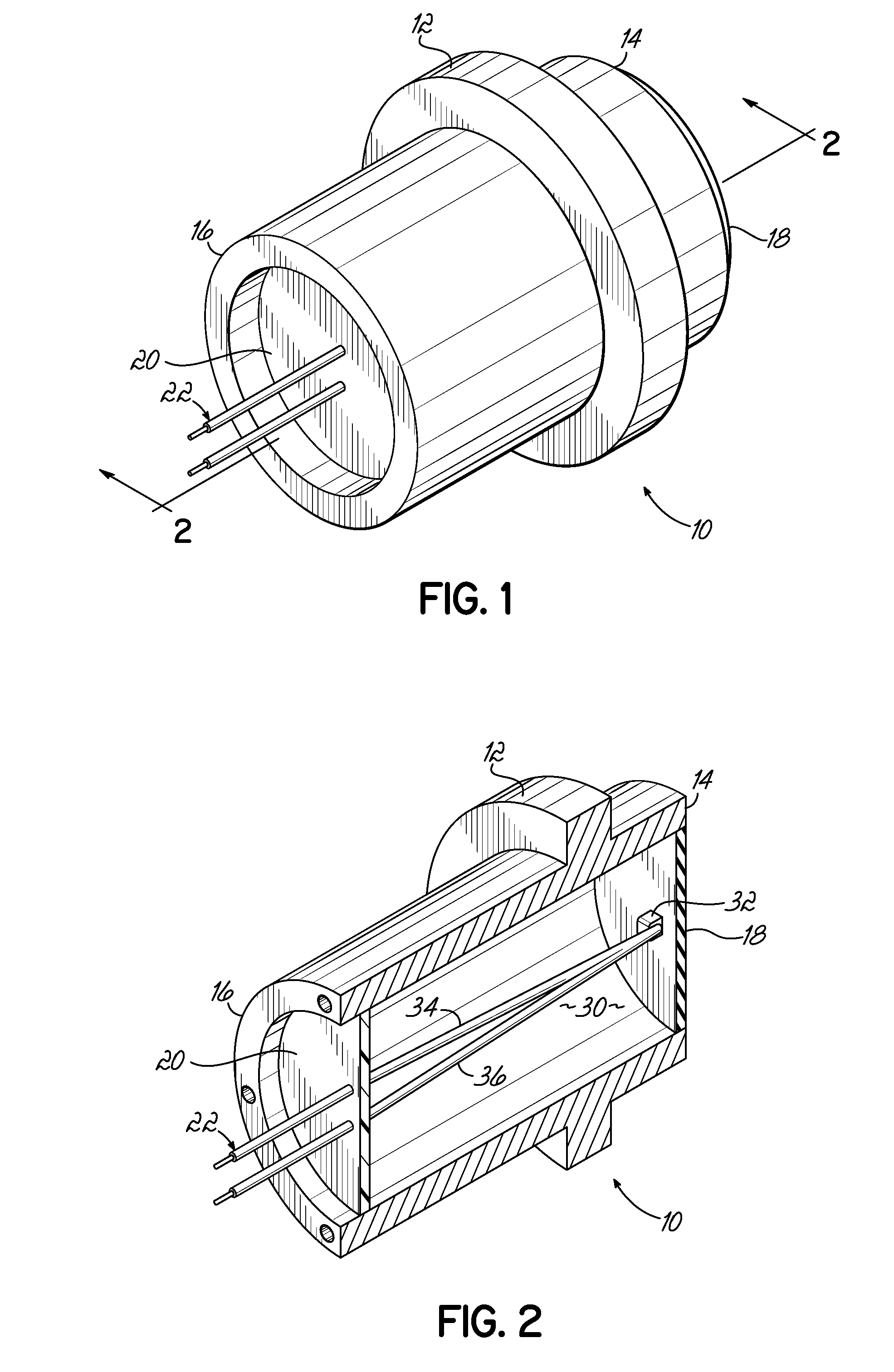
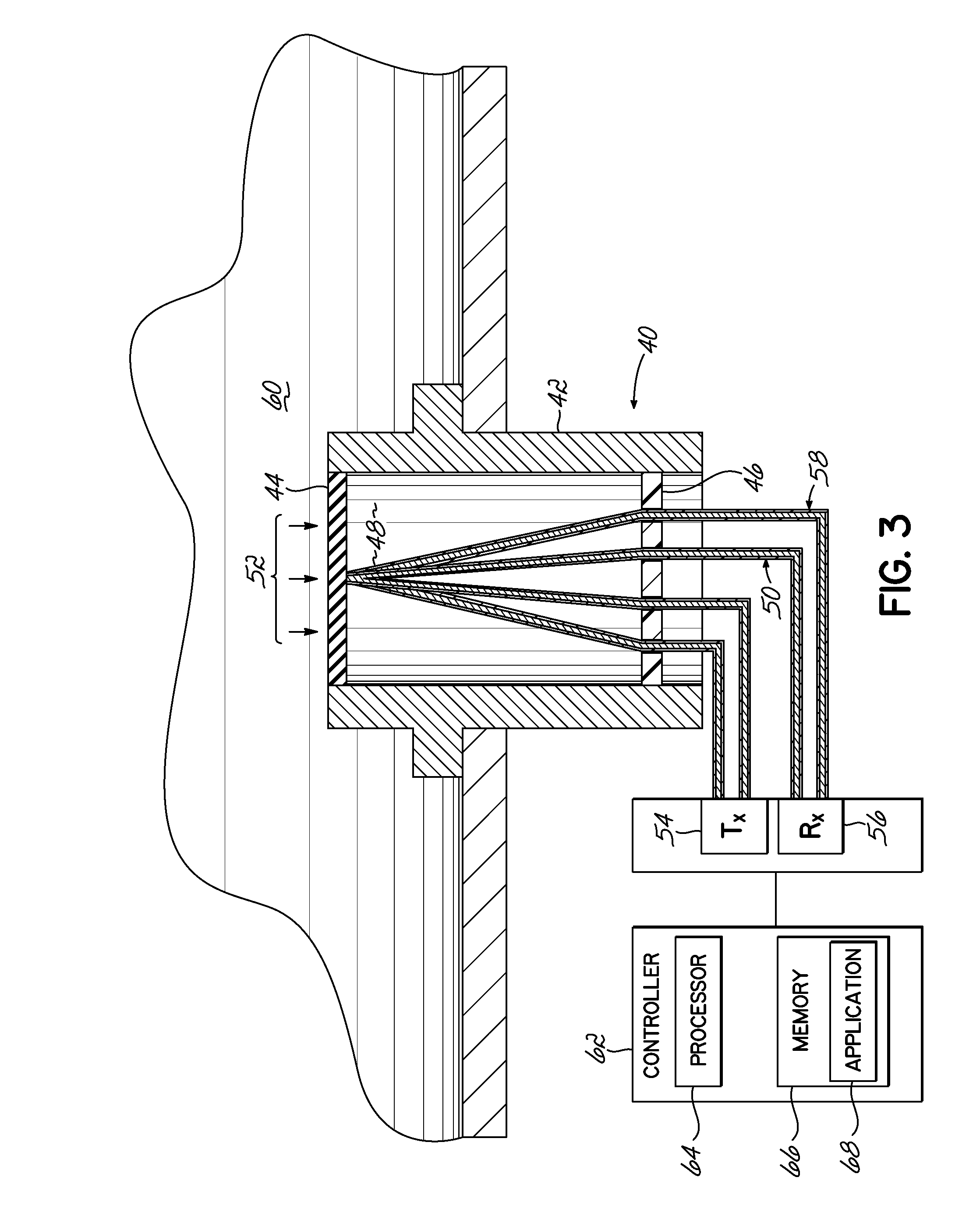
[0037]Embodiments of the invention are generally directed to a sensor and a sensing method, in which signals communicated over one or more wires are monitored such that environmental conditions may be measured based at least in part on characteristics of the communicated signals, where the environmental conditions include pressure, force, temperature, strain, and / or vibration.

[0038]In some embodiments consistent with the invention, a pressure sensor may comprise a housing having a first and second end. A diaphragm may be coupled to the housing, proximate the first end, and an attachment plate may be coupled to the housing, such that an interior is defined within the housing and between the diaphragm and the attachment plate. A wire may be coupled in tension between the attachment plate and the diaphragm, such that the wire exhibits a varying ultrasonic signal transmission characteristic as the tension between the attachment plate and the diaphragm changes.

[0039]As discussed above, c...


PUM


Abstract

Systems and methods for measuring environmental conditions of a sensing location, where a sensor including a measuring surface and a wire coupled in tension to the measuring surface over which ultrasonic signals may be transmitted and sensed. Signal analysis of ultrasonic signals transmitted over the tensioned wire are analyzed to measure one or more environmental conditions acting on the measuring surface.

Description

GOVERNMENT RIGHTS[0001]Certain aspects of this invention were made with government support under Grant / Contract No. N68335-10-C-0165 and N68335-10-C-0351 awarded by the Naval Air Warfare Center (NAVAIR). The U.S. Government may have certain rights in the invention.FIELD OF THE INVENTION[0002]The present invention relates to sensing technology, and more particularly to sensors and sensing methods.BACKGROUND OF THE INVENTION[0003]Many conventional mechanical systems are monitored to determine operating conditions such as pressure, temperature, vibrations, etc. However, in many systems it is desirable to monitor and measure operating conditions at locations in the system where it is extremely difficult to do so. For example, the measurement environment may be a harsh environment in which sensors are unable to operate reliably. For example, monitoring an aero gas turbine engine presents unique challenges due to the harsh environmental conditions of the engine, i.e., high temperatures, h...

Claims


Application Information

Patent Timeline
IPC IPC(8): G01L5/04
CPCG01L11/06G01L9/0013
Inventor ROTH, II, RICHARD ALLANLARSEN, CHRISTOPHER GEORGESHELLEY, STUART JAMESNIEHAUS, LOGAN ALEXANDER
Owner ETEGENT TECH
Learn More