Fluid migration shut-off

a technology of fluid migration and shut-off, which is applied in the direction of fluid removal, earthwork drilling and mining, and wellbore/well accessories, etc., can solve the problems of debris caught in the valve, wear or degradation of the valve, and the performance of the check valve is not always adequate to prevent all fluid migration

Inactive Publication Date: 2012-12-27
BAKER HUGHES INC
View PDF7 Cites 4 Cited by
  • Summary
  • Abstract
  • Description
  • Claims
  • Application Information

AI Technical Summary

Problems solved by technology

The performance of these check valves is not always adequate to prevent all fluid migration, particularly under static conditions (no chemical being injected) or while chemicals are being injected at lower rates.
Problems with check valves may include debris caught in the valves, wear or degradation of the valves over time, problematic installations, etc.

Method used


Image

  • Fluid migration shut-off
  • Fluid migration shut-off
  • Fluid migration shut-off

Examples


Embodiment Construction

[0014]A detailed description of one or more embodiments of the disclosed apparatus and method are presented herein by way of exemplification and not limitation with reference to the Figures.

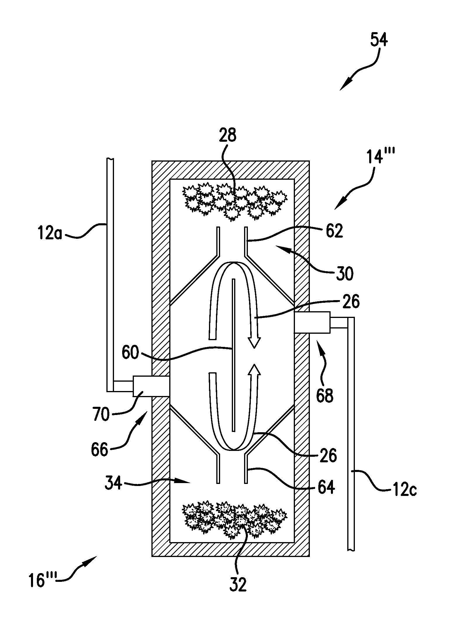
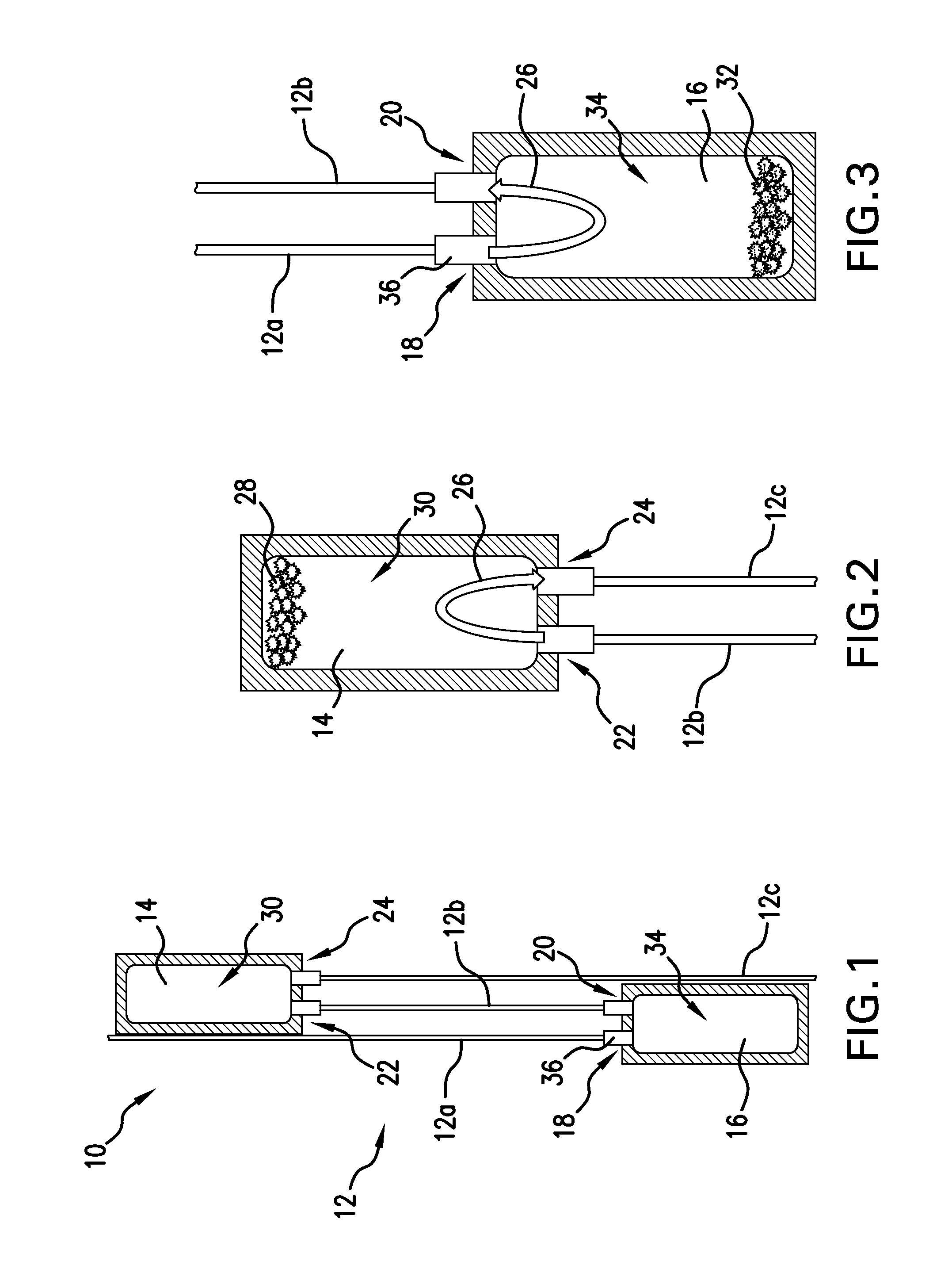
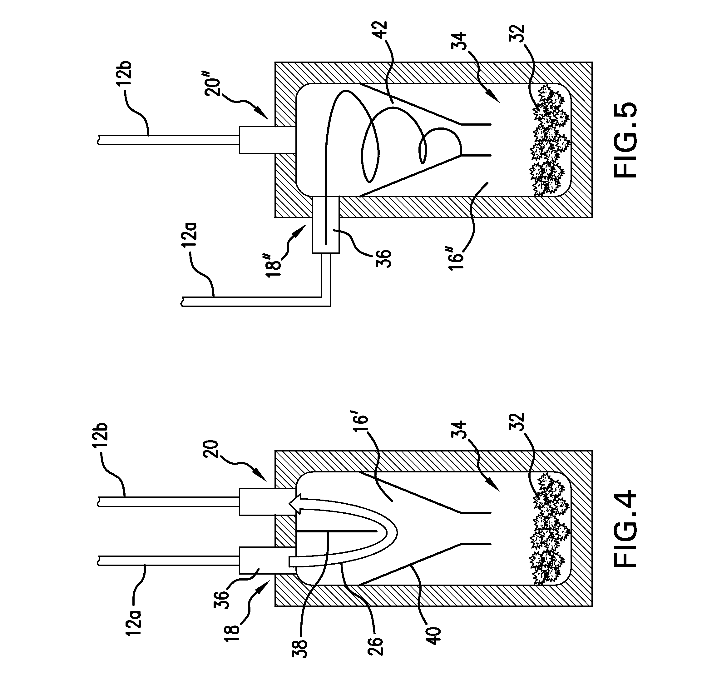
[0015]Referring now to FIG. 1, an assembly 10 is shown. The assembly 10 is included along a chemical injection line 12. The chemical injection line 12 is arranged in a borehole spanning between a surface in which the borehole is made (e.g., a surface of the Earth) and production tubing in the borehole for enabling operators at the surface to inject chemicals or the like downhole, such as demulsifiers, clarifiers, corrosion inhibitors, scale inhibitors, dewaxers, surfactants, etc., for aiding in production. The assembly 10 is arranged to prevent the migration of natural gas or other fluids, up the injection line 12 to the surface.

[0016]The assembly 10 includes a trap 14 and a debris catch 16. The chemical injection line 12 comprises several sections, namely, lines 12a, 12b, and 12c. The line 12a i...


PUM


Abstract

A downhole assembly, including a line operatively arranged to carry a first fluid, and a trap arranged in fluid communication with the line, the trap operatively arranged to enable the first fluid to flow in a first direction, while capturing a second fluid in a compartment, thereby preventing migration of the second fluid through the line in a second direction opposite to the first direction.

Description

CROSS REFERENCE TO RELATED APPLICATIONS[0001]This application claims the benefit of an earlier filing date from U.S. Provisional Application Ser. No. 61 / 500,995 filed Jun. 24, 2011, the entire disclosure of which is incorporated herein by reference.BACKGROUND[0002]Chemical injection systems are used in the downhole drilling and completions industry. Check valves are included to prevent natural gas and other fluids from undesirably migrating up through the chemical injection lines. The performance of these check valves is not always adequate to prevent all fluid migration, particularly under static conditions (no chemical being injected) or while chemicals are being injected at lower rates. Problems with check valves may include debris caught in the valves, wear or degradation of the valves over time, problematic installations, etc. Accordingly, advances in preventing fluid migration are always well received by the industry.BRIEF DESCRIPTION[0003]A downhole assembly, including a line...

Claims


Application Information

Patent Timeline
Patent Type & Authority Applications(United States)
IPC IPC(8): E21B43/38E21B27/00
CPCE21B27/00
Inventor REES, ROBERT S.LAFLEUR, LOUIS F.
Owner BAKER HUGHES INC
Why Eureka
Try Eureka