Vascular plug having composite construction

a technology of vascular plugs and composites, which is applied in the field of vascular plugs having composite construction, can solve the problems of time-consuming and expensive procedures, requiring as much as an hour of physician's or nurse's time, and uncomfortable for patients, so as to reduce the likelihood of leaking, increase the effective radial dimension of the sealing member, and facilitate the delivery of the sealing member

Inactive Publication Date: 2005-12-01
CARDINAL HEALTH SWITZERLAND 515 GMBH
View PDF99 Cites 256 Cited by
  • Summary
  • Abstract
  • Description
  • Claims
  • Application Information

AI Technical Summary

Benefits of technology

[0018] Preferably, the tether is attached to the sealing member and is adapted to extend proximally from the sealing member, through and out of the incision, thereby allowing for manipulation by the user. The tether may be used to adjust the sealing member after its deployment, such as by increasing the effective radial dimension of the sealing member, or to remove the sealing member altogether if necessary.
[0019] In several preferred embodiments, the sealing device has a composite structure that includes one or more sealing members, as described above, and one or more restraining members. Preferably, the restraining member provides the ability to more easily deliver a sealing member and the ability to reduce the likelihood that the sealing member will migrate after its deployment. In a particular prefer

Problems solved by technology

This procedure, however, may be time consuming and expensive, requiring as much as an hour of a physician's or nurse's time.
It is also uncomfortable for the patient, and requires that the patient remain immobilized in the operating room, catheter lab, or holding area.
In addition, a risk of hematoma exists from bleeding before hemostasis occurs.
Such devices, however, may be difficult to position properly with respect to the vessel, which may be particularly significant since it is generally undesirable to expose the plug material, e.g., collagen, within the bloodstream, where it may float downstream and risk causing an embolism.
Percutaneous suturing devices, howev

Method used


Image

  • Vascular plug having composite construction
  • Vascular plug having composite construction
  • Vascular plug having composite construction

Examples


Embodiment Construction

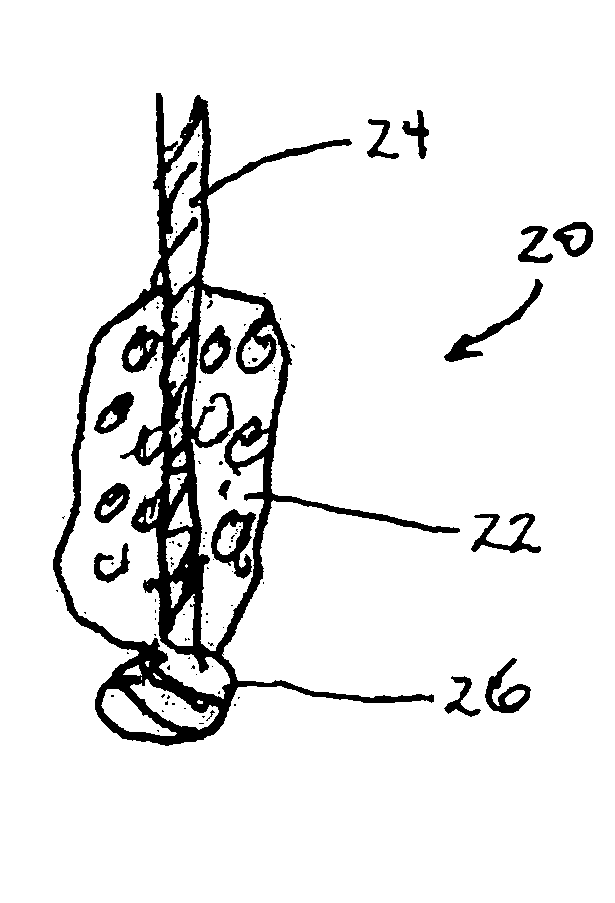
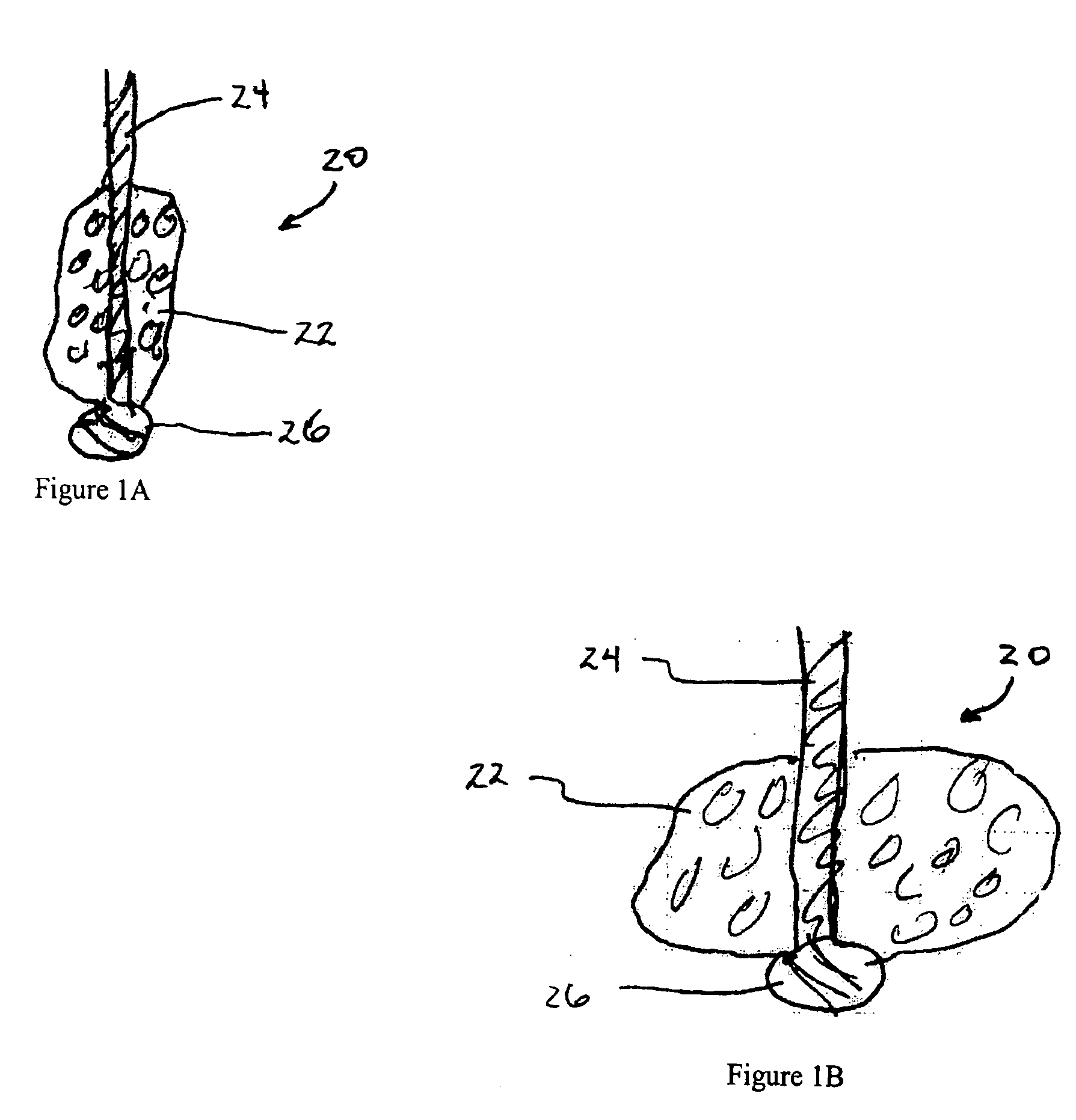
[0055]FIGS. 1A and 1B are rudimentary illustrations of a vascular sealing device in accordance with the present invention. The device 20 includes a sealing member 22 retained on a tether 24. The sealing member 22 is preferably retained on the tether 24 at or near its distal end point by a stop member 26 formed at the distal end of the tether 24. The stop member 26 is preferably a knot formed at the distal end of the tether 24. FIG. 1A shows the device in its unexpanded, predeployment state. FIG. 1B shows the device after it has expanded due to fluid exposure.

[0056] The sealing member 22 is formed from a material that is able to expand, or to be expanded, once the sealing device 22 is deployed for use. The sealing member is preferably formed from a bioabsorbable material, but, in several alternative embodiments, the sealing member may be formed from a non-bioabsorbable material. Examples of suitable bioabsorbable materials include bioabsorbable collagen, polyglycolic acids (PGAs), p...


PUM


Abstract

This invention relates to apparatus and methods for use in sealing a vascular puncture site, particularly sites of punctures that are the result of catheterization or other interventional procedures. In several of the preferred embodiments, the sealing device includes a sealing member and a tether. The sealing member generally performs the function of occupying a space in an incision, puncture, or other wound and sealing the space in the incision, puncture, or wound that it occupies, to prevent further blood flow. The tether is typically attached in some manner to the sealing member, and provides the user with the ability to withdraw the sealing member if necessary. In a particularly preferred form, the sealing device further includes a restraining member associated with the sealing member. The restraining member provides the ability to more securely restrain the sealing member to prevent it from migrating from the deployment location within a tissue tract. The restraining member may also provide an additional capability of manipulating the sealing member after deployment.

Description

RELATED APPLICATION [0001] This patent application is a continuation-in-part of U.S. patent application Ser. No. 10 / 142,735, filed May 10, 2002, which is a continuation-in-part of U.S. patent application Ser. No. 09 / 866,548, filed May 25, 2001, which is a continuation-in-part of U.S. patent application Ser. No. 09 / 738,431, filed Dec. 14, 2000, the disclosures of which are expressly incorporated by reference herein.FIELD OF THE INVENTION [0002] The present invention relates generally to apparatus and methods for sealing or closing passages through tissue, and more particularly to devices for sealing punctures or other openings communicating with body lumens, such as blood vessels. BACKGROUND OF THE INVENTION [0003] Catheterization and interventional procedures, such as angioplasty or stenting, generally are performed by inserting a hollow needle through a patient's skin and muscle tissue into the vascular system. A guide wire may then be passed through the needle lumen into the patie...

Claims


Application Information

Patent Timeline
IPC IPC(8): A61B17/00A61B17/08
CPCA61B17/0057A61B17/12022A61B17/12109A61B17/12159A61B17/12163A61B2017/00004A61B17/1219A61B2017/00654A61B2017/00778A61B2017/00898A61B17/12172
Inventor GINN, RICHARD S.PALERMO, THOMAS J.OLSEN, PHILHARTRIDGE, TELLISSHIVELY, ADAM
Owner CARDINAL HEALTH SWITZERLAND 515 GMBH
Why Eureka
Try Eureka