Locking mechanisms and associated methods

Active Publication Date: 2009-04-23
SPINESMITH PARTNERS
View PDF60 Cites 242 Cited by
  • Summary
  • Abstract
  • Description
  • Claims
  • Application Information

AI Technical Summary

Benefits of technology

[0006]An apparatus of the invention is provided for a medical device including an implant, one or more fasteners configured to secure the implant in an implanted position, a recess formed in the implant, a movable device coupled to the implant, the movable device having a locked position and an unlocked positio

Problems solved by technology

One problem with securing surgical implants with screws or other fasteners relates to fastener migration.
After fixation, fasteners may tend to gradually become loose, which is undesirable.
In addition, as fasteners become loose, they may protrude outward and can be a source of discomfort and potentia

Method used


Image

  • Locking mechanisms and associated methods
  • Locking mechanisms and associated methods
  • Locking mechanisms and associated methods

Examples


Example

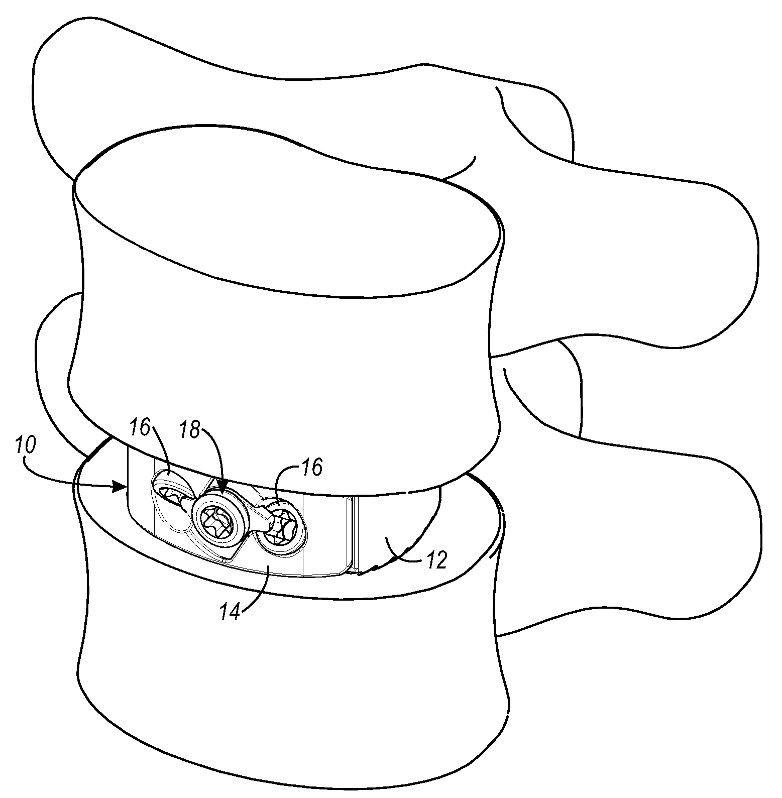
[0027]The present invention relates to locking mechanisms used with surgical implants for use in various medical applications. Numerous types of surgical implants use fasteners such as screws or pins to fix the implant in place. Examples of surgical implants that may secured using fasteners includes bone plates, spinal fusion devices, intervertebral spinal devices, artificial joints, etc. The present invention will be described using several examples of surgical implants, but it should be understood that locking devices of the present invention can be used with any desired implant.

[0028]FIG. 1 is an isometric view of one example of an anti-backout device of the present invention. In this example, the anti-backout device is shown being used with an interbody fusion device, although the anti-backout device may be used with any desired type of surgical implant. FIG. 1 shows a surgical implant 10, including a load bearing device 12, and a retention device 14. FIG. 1 also shows two bone ...


PUM


Abstract

A method and apparatus is provided for use with a surgical implant to secure fasteners, such as bone screws or pins. An anti-backout mechanism is used to preventing migration of the fasteners after the implant is installed. In one example, an anti-backout mechanism includes a locking plate having a locked position and an unlocked position. The locking plate has one or more protrusions that are configured to prevent migration the fasteners when the locking plate is in the locked position.

Description

CROSS REFERENCE TO RELATED APPLICATIONS[0001]This application claims priority under 35 U.S.C. §119 to co-pending, commonly owned U.S. provisional patent application No. 60 / 981,358, attorney docket number SPU.P0105P, filed on Oct. 19, 2007, entitled “LOCKING MECHANISMS AND ASSOCIATED METHODS,” (pending) which is incorporated by reference herein.FIELD OF THE INVENTION[0002]This invention relates to the field of surgical implants. In particular, this invention is drawn to anti-backout, or locking mechanisms for surgical implants.BACKGROUND OF THE INVENTION[0003]It is common for surgical implants to be secured in place using screws or other fasteners. One problem with securing surgical implants with screws or other fasteners relates to fastener migration. After fixation, fasteners may tend to gradually become loose, which is undesirable. In addition, as fasteners become loose, they may protrude outward and can be a source of discomfort and potentially cause trauma to nearby tissue.[0004...

Claims


Application Information

Patent Timeline
IPC IPC(8): A61F2/44A61B17/04
CPCA61B17/7059A61B17/8042A61F2/30744A61F2/4465A61F2002/30517A61F2220/0025A61F2002/30604A61F2002/30672A61F2002/30892A61F2002/4475A61F2002/30578A61F2002/30593
Inventor JONES, ROBERT J.LEAK, TIMOTHY J.
Owner SPINESMITH PARTNERS
Why Eureka
Try Eureka