Apparatus and method for making gas-filled filling bodies

Active Publication Date: 2008-09-18
LORSCH JOHANNES
View PDF14 Cites 0 Cited by
  • Summary
  • Abstract
  • Description
  • Claims
  • Application Information

AI Technical Summary

Benefits of technology

[0012]According to another feature of the present invention, a braking mechanism may be provided for decelerating an unwinding of the plastic film from the supply reel so that the plastic film is held taut between the supply reel and the drive unit. In this way, air is prevented from escaping the pockets during advance of the plastic film through the gas filling device and downstream thereof. Operation of the brake mechanism may be triggered automatically or by hand. As a result of the provision of the brake mechanism, the respectively detached upper and lower film portions bear upon the gas filling device and thus prevent release of air and thereby reduce air losses.
[0013]Escape of injected air can also be prevented by implementing the welding operation as close as possible following the injection of air so that certain residual leaks do not significantly affect the filling degree of the filling bodies. According to another feature of the present invention, the drive unit may hereby be constructed to include two electric motor driven rollers which abut one another in a circumferential region and are each provided with a friction layer, and between which a border area of the plastic film is guided, as the plastic film moves in the transport direction. Suitably, the two rollers are disposed in offset relationship in horizontal direction.
[0014]According to another feature of the present invention, an upper one of the rollers is positioned in transport direction of the plastic film offset behind the lower one of the rollers, with the lower roller spatially following immediately t

Problems solved by technology

This apparatus is complex and requires substantial maintenance works as a result of the use of Teflon-coated steel.
The respective drive devices with gear mechani

Method used


Image

  • Apparatus and method for making gas-filled filling bodies
  • Apparatus and method for making gas-filled filling bodies
  • Apparatus and method for making gas-filled filling bodies

Examples


Example

[0025]Throughout all the figures, same or corresponding elements may generally be indicated by same reference numerals. These depicted embodiments are to be understood as illustrative of the invention and not as limiting in any way. It should also be understood that the figures are not necessarily to scale and that the embodiments are sometimes illustrated by graphic symbols, phantom lines, diagrammatic representations and fragmentary views. In certain instances, details which are not necessary for an understanding of the present invention or which render other details difficult to perceive may have been omitted.

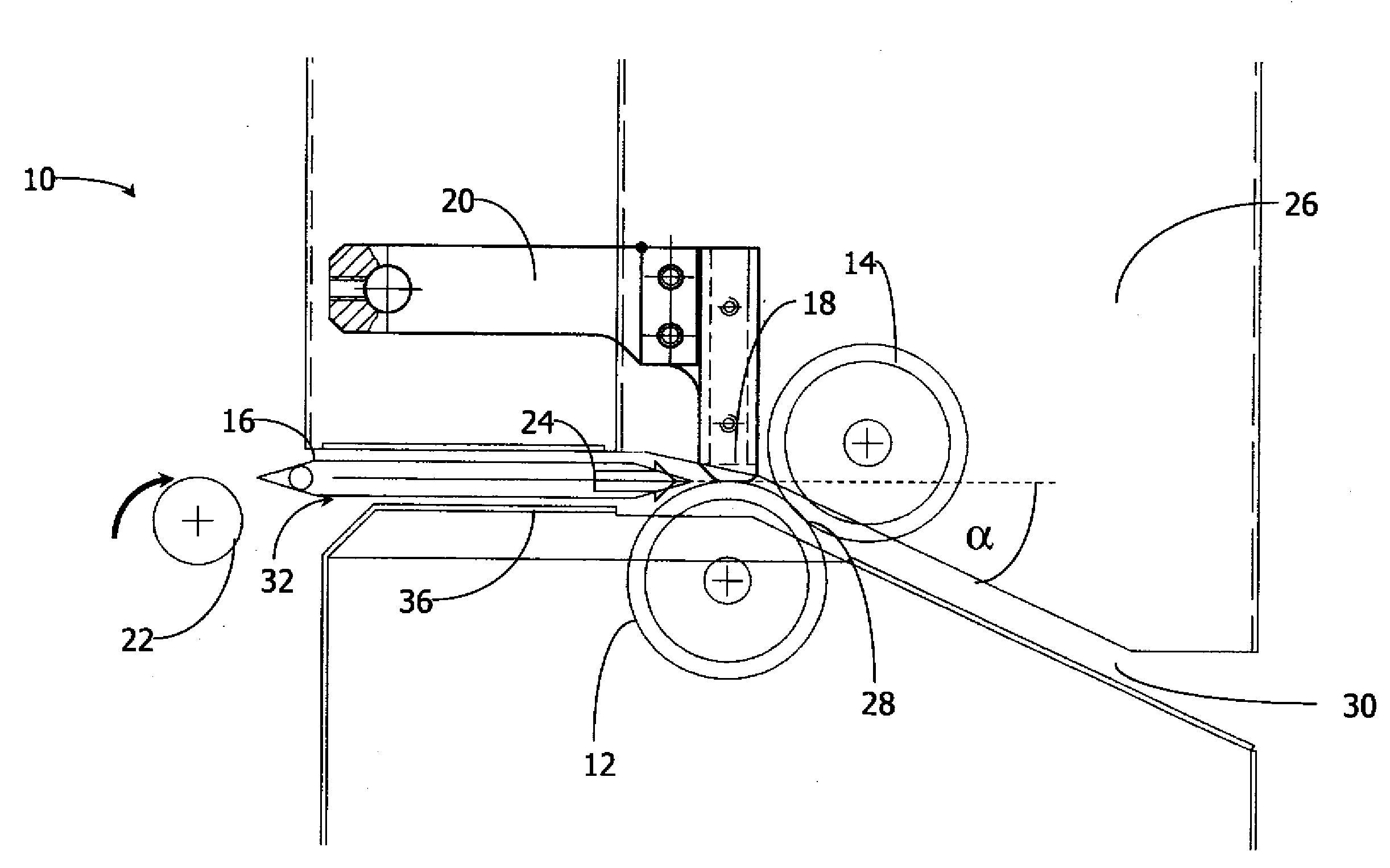
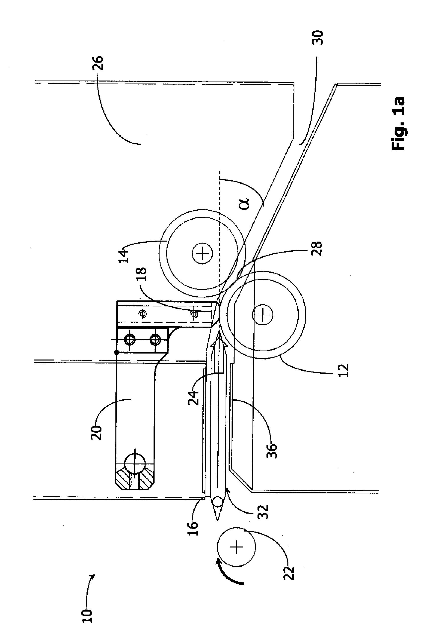
[0026]Turning now to the drawing, and in particular to FIG. 1a, there is shown a fragmentary schematic side view of an apparatus in accordance with the present invention, generally designated with reference numeral 10, for making gas-filled filling bodies from a half-tubular film 40 made of plastic. A specific construction of such a plastic film 40 is fully described in inte...


PUM


Abstract

Apparatus for making gas-filled filling bodies includes a supply reel for storing a pre-fabricated half-tubular plastic film having an at least partially open border side and being divided into individual pockets by weld seams which extend transversally with respect to a transport direction of the plastic film. Positioned downstream of the reel and receiving the plastic film from the reel is a gas filling device for blowing air into the pockets. Positioned downstream of the gas filling device and receiving the plastic film from the gas filling device is a welding tool for welding the open border side of the plastic film for formation of closed filling bodies. The transport of the film through the apparatus is realized by a drive unit which applies a force upon the plastic film essentially downstream of the gas filling device, as viewed in the transport direction.

Description

CROSS-REFERENCES TO RELATED APPLICATIONS[0001]This application claims the benefit of prior filed U.S. provisional Application No. 60 / 956,284, filed Aug. 16, 2007, pursuant to 35 U.S.C. 119(e), the content of which is incorporated herein by reference in its entirety as if fully set forth herein.[0002]This application also claims the priorities of German Patent Application, Serial No. 10 2006 045 793.5, filed Sep. 26, 2006, and European Patent Application 07113747.5, filed Aug. 2, 2007 pursuant to 35 U.S.C. 119(a)-(d), the contents of which are incorporated herein by reference in its entirety as if fully set forth herein.BACKGROUND OF THE INVENTION[0003]The present invention relates, in general, to an apparatus and method for making gas-filled filling bodies.[0004]Nothing in the following discussion of the state of the art is to be construed as an admission of prior art.[0005]Gas-filled—normally air-filled—filling bodies are increasingly used as filling material for transport of sensi...

Claims


Application Information

Patent Timeline
IPC IPC(8): B65B31/00
CPCB31D5/0073B31D2205/0058B31D2205/0052
Inventor LORSCH, JOHANNES
Owner LORSCH JOHANNES
Why Eureka
Try Eureka