Method and apparatus for imaging in an eye

a technology of optical imaging and eye, applied in the field of optical imaging, can solve problems such as the difficulty of imaging certain types of cells in the retinal area

Active Publication Date: 2012-12-27
UNIVERSITY OF ROCHESTER
View PDF1 Cites 5 Cited by
  • Summary
  • Abstract
  • Description
  • Claims
  • Application Information

AI Technical Summary

Problems solved by technology

In the past, it was difficult to image certain types of cells in the area of the retina, unless the cells had been excised from the subject's body.

Method used


Image

  • Method and apparatus for imaging in an eye
  • Method and apparatus for imaging in an eye
  • Method and apparatus for imaging in an eye

Examples


Embodiment Construction

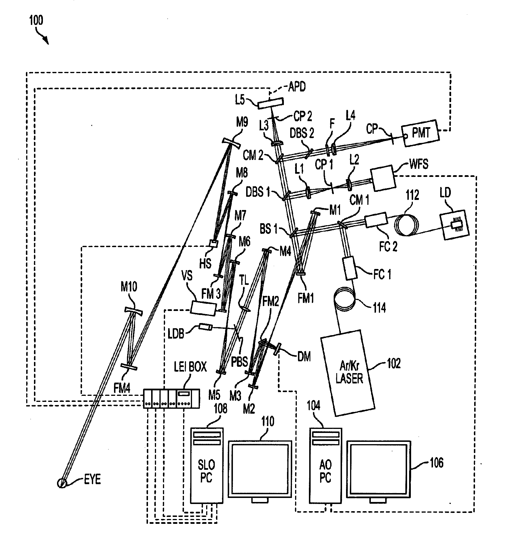
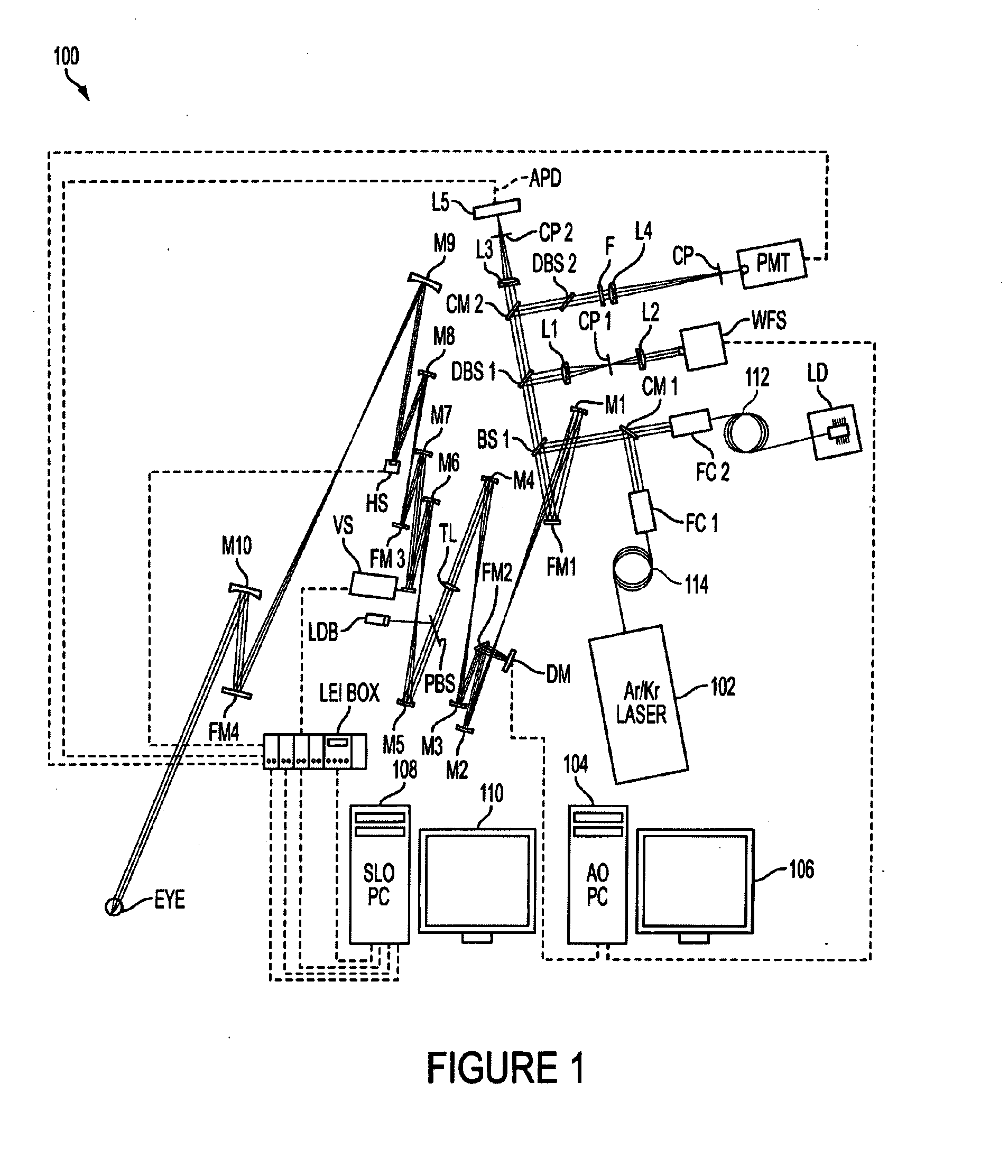
[0042]Referring now to the drawings, wherein like reference numerals designate the same or corresponding parts throughout the several views, FIG. 1 illustrates a non-limiting example of an adaptive optics scanning laser ophthalmoscope (AOSLO) 100. Due to the relatively high magnification and reduced impact of higher order aberrations in the AOSLO shown in FIG. 1, fine structures such as ganglion cell axons can be resolved.

[0043]Retinal ganglion cells are of interest because they provide the retinal output signal to the brain, the functional role is unknown for most of the 15-20 morphologically distinct ganglion cell classes, and they are one of the most vulnerable retinal cells to eye disease. Ganglion cell loss is the cause of blindness in glaucoma, the most prevalent cause of irreversible blindness in the United States. However, ganglion cells are difficult to image because their reflectance is roughly 60 times less than that of cones and they are entangled with Muller and amacrin...


PUM


Abstract

A scanning laser ophthalmoscope (SLO) that includes at least one adjustable scanning system adapted for a variable field of view; at least one light source having at least a first spectral emission band suitable to effect at least one of a fluorescence signal and a reflectance signal from a retinal cell; and at least one detector configured to detect at least two different spectral bands from the at least one of the fluorescence and reflectance signals.

Description

RELATED APPLICATION DATA[0001]This application is a divisional of U.S. application Ser. No. 11 / 798,902 filed on May 17, 2007 and claims priority thereto as well as to U.S. Provisional Patent Application Ser. No. 60 / 801,059, filed May 18, 2006, the entire contents of which are hereby incorporated by reference.[0002]The present invention may be related to the inventions described and claimed in U.S. Pat. No. 5,777,719; U.S. Pat. No. 5,949,521; U.S. Pat. No. 6,095,651; U.S. patent application Ser. No. 10 / 529,067, filed Dec. 23, 1997 and entitled Apparatus for Improving Vision and Retinal Images; U.S. Pat. No. 6,338,559; U.S. Pat. No. 6,379,005; and U.S. Pat. No. 6,890,076, the contents of each of which are herein incorporated by reference.FEDERALLY SPONSORED RESEARCH[0003]The invention described in this application was supported by NIH Grant BRP-EY014375; NIH Training Grant EY07125; NIH Core Grant EY001319; NSF Grant CFAO-AST-9876783; and NIH Grant EY014375. The US Government has certa...

Claims


Application Information

Patent Timeline
Patent Type & Authority Applications(United States)
IPC IPC(8): A61B3/10
CPCG06T5/50G06T7/0012G06T2207/10056A61B3/14G06T2207/30024G06T2207/30041G06T2207/10064A61B3/1025G06V20/695
Inventor WILLIAMS, DAVIDMORGAN, JESSICA WOLFINGGRAY, DANIELDUBRA, ALFREDO
Owner UNIVERSITY OF ROCHESTER
Why Eureka
Try Eureka