Novel materials used for emitting light

A technology of emission spectrum and composition, applied in the field of visible light materials, can solve problems such as poor performance

Inactive Publication Date: 2008-06-25
ETECH INC +1
View PDF3 Cites 20 Cited by
  • Summary
  • Abstract
  • Description
  • Claims
  • Application Information

AI Technical Summary

Problems solved by technology

One problem with making this transition is that known and existing phosphors are

Method used


Image

  • Novel materials used for emitting light
  • Novel materials used for emitting light
  • Novel materials used for emitting light

Examples


Embodiment Construction

[0035] In order to demonstrate the effectiveness of the method of the present invention, a number of systems have been investigated, including:

[0036] - doped with Eu 2+ Alkaline earth metal orthosilicates, especially Ca 2 SiO 4 、Sr 2 SiO 4 and Ba 2 SiO 4 , wherein the dopant can be a fluoride or oxide of a rare earth metal (to show the heteroatom effect of fluoride-into-oxide (fluoride-into-oxide)), the dopant concentration range is 0.5mol%~ 2.5mol%, the calcination temperature range is 700°C-900°C, and the reduction temperature range is 900°C-1100°C.

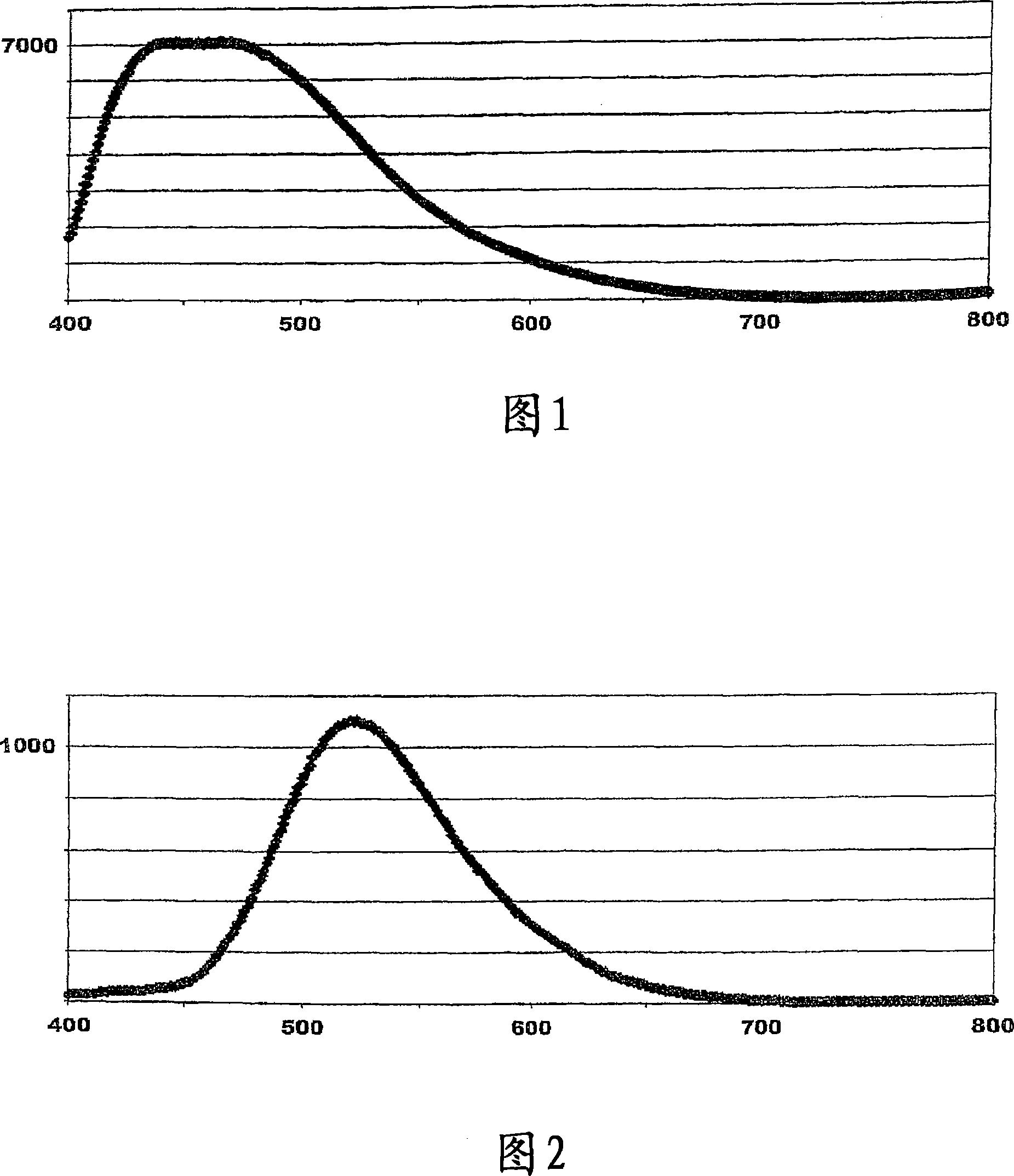
[0037] - in Ba 2 SiO 4 In the system, at all doping levels, the emission of the fluoride-doped system at 254nm and 366nm UV is clearly shifted to higher wavelengths, which is more obvious when combining the lowest calcination temperature and the highest reduction temperature (dark green).

[0038] - in Sr 2 SiO 4 In systems, fluoride doping generally shifts the emission to higher wavelengths.

[0039] - Alkaline ...


PUM


Abstract

An luminescent composition comprises a mixture of two or more materials, emitting electromagnetic radiation when subject to stimuli, wherein the spectral emission is not calculable at a first approximation as the simple weighted sum of the spectral emissions of the materials independently subject to said stimuli. Especially advantageous compositions are achieved if the anionic matrix is an oxide and the doping anionic salt is a fluoride or vice versa.

Description

technical field [0001] The present invention relates to materials that emit electromagnetic radiation, especially visible light, when an excitation is provided. Background technique [0002] Certain materials, including natural minerals, are known to emit electromagnetic radiation, especially visible light (electromagnetic radiation in the human visible part of the spectrum, with wavelengths around 400nm to 700nm), when provided with appropriate excitation. The excitation can be electromagnetic radiation of a different nature, usually of a lower wavelength (higher frequency), where the phenomenon is known as fluorescence or phosphorescence, and the excitation radiation can be, for example, ultraviolet light: the excitation can also be, for example, high-energy Electrons or ions, the former involving direct (circuit) or indirect (electron bombardment) electrical contact. Other incentives are also possible. [0003] For the purpose of emitting light, especially of interior o...

Claims


Application Information

Patent Timeline
IPC IPC(8): C09K11/77C09K11/64C09K11/57C09K11/62C09K11/60
CPCY02B20/181
Inventor 弗兰克・库贝尔
Owner ETECH INC
Why Eureka
Try Eureka