Bottling installation including filler spouts fitted with feed-back ducts from the spout bodies

a technology of feed-back ducts and bottling spouts, which is applied in the direction of liquid bottling, packaging goods type, cleaning of filling devices, etc., can solve the problems of very small quantity of product wasted and very fast filling, and achieve reliable bottling installation, minimize both the quantity of product lost and the amount of water consumed.

Active Publication Date: 2013-01-03
SERAC GROUP
View PDF12 Cites 19 Cited by
  • Summary
  • Abstract
  • Description
  • Claims
  • Application Information

AI Technical Summary

Benefits of technology

[0010]An object of the invention is to provide a reliable bottling installation for bottling a product liquid in containers, making i

Problems solved by technology

This initial filling is therefore very fast and th

Method used


Image

  • Bottling installation including filler spouts fitted with feed-back ducts from the spout bodies
  • Bottling installation including filler spouts fitted with feed-back ducts from the spout bodies

Examples


Embodiment Construction

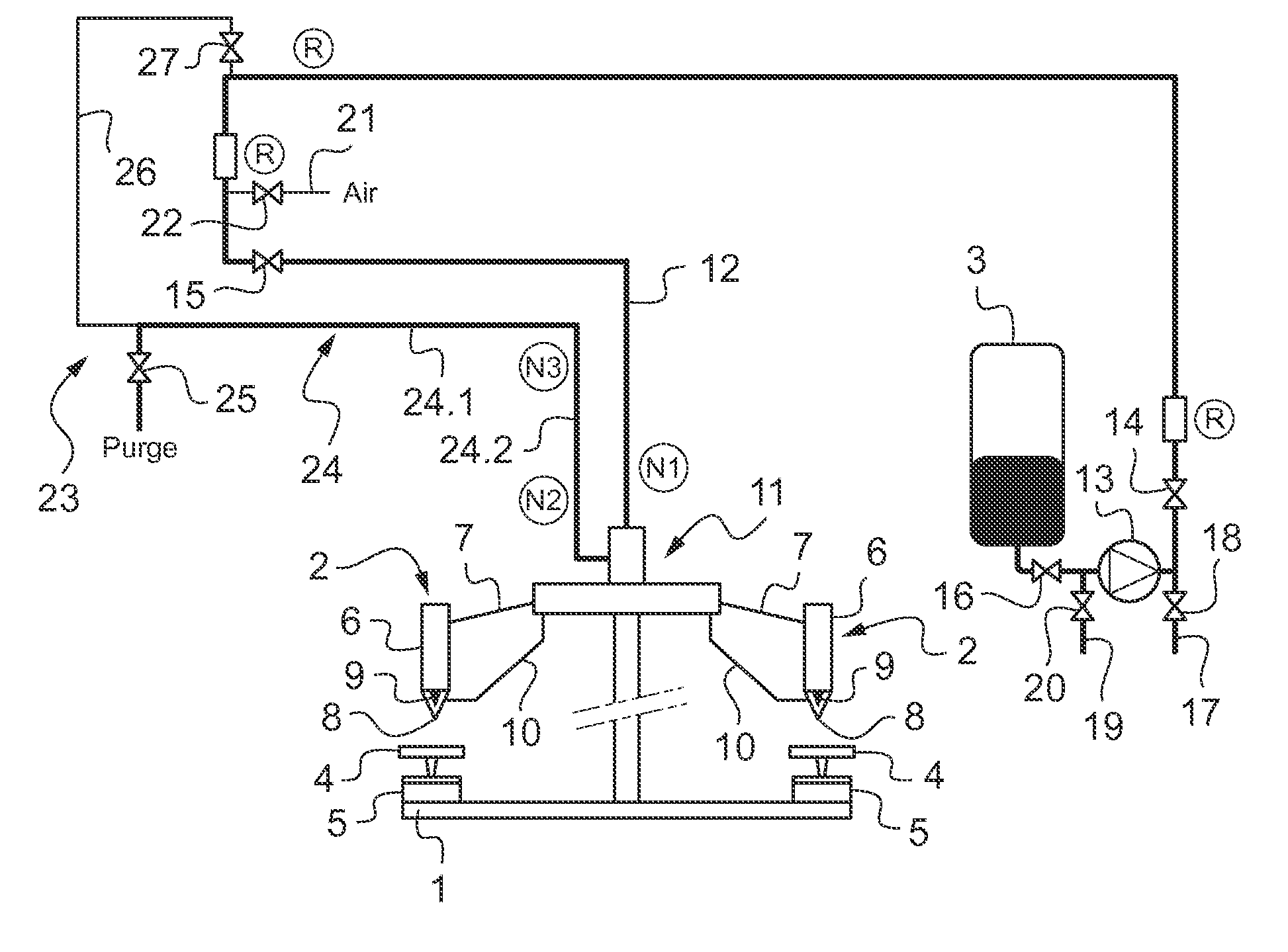
[0016]With reference to FIG. 1 and in known manner, the filler installation shown comprises a rotary carrousel comprising a rotary stand 1 carrying the filler stations, each comprising a filler spout 2 and a support member 4 for supporting a container directly below the filler spout, each support member 4 being associated with a weighing member 5 acting together with a control unit (not shown) in order to control the corresponding filler spout.

[0017]Each filler spout 2 comprises a spout body 6 having a top end connected to a feed duct 7 of the filler spout and a bottom end provided with an orifice 8 fitted with a controlled valve 9.

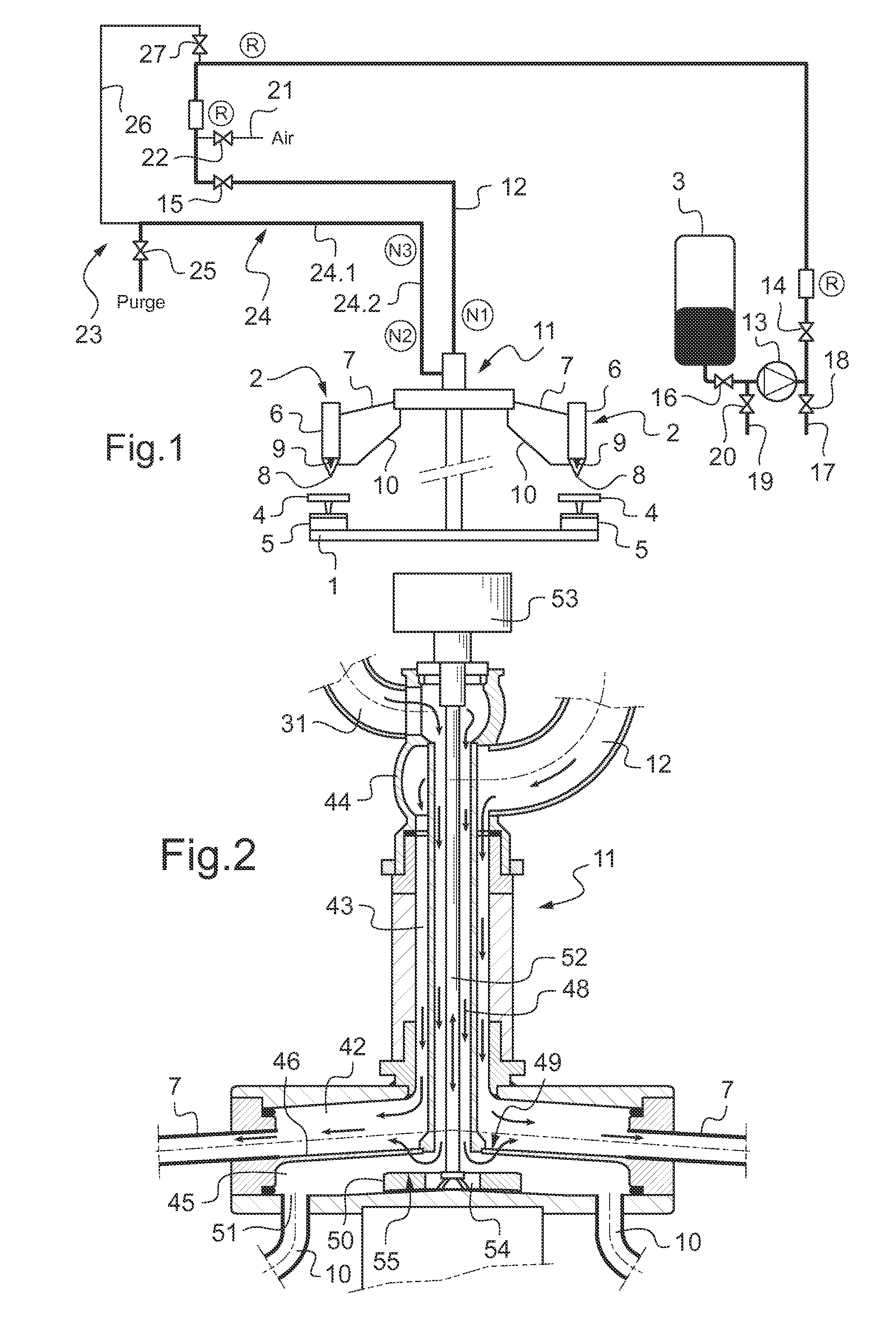
[0018]In the invention, each filler spout 2 is further fitted with a feed-back duct 10 having one end fastened to the spout body 6 and opening out into the body of the spout above the valve 9, and an opposite end connected to a multi-channel connection member 11, or diffuser, the structure of which is described below with reference to FIG. 2. The multi-ch...


PUM

PropertyMeasurementUnit
Symmetryaaaaaaaaaa

Abstract

The bottling installation for bottling a liquid in containers includes at least one filler terminal comprising a filler spout (2) comprising a spout body having a top end portion connected to a filler spout feed duct (7) and a bottom end provided with an orifice (8) fitted with a controlled valve, the filler spout being fitted with a feed-back duct (10) opening out into the spout body (6) above the controlled valve (9) and suitable for being connected by a connection member (11) to a general feed duct (12) between a stop valve (14) and an isolating valve (15), a purge valve (17) being connected to the general feed duct (12) between the isolating valve (15) and the connection member (11).

Description

[0001]The present invention relates to a bottling installation for bottling a product liquid in containers.BACKGROUND OF THE INVENTION[0002]Bottling installations for bottling a liquid are known that comprise a series of filler terminals, each comprising a filler spout and a support member for supporting a container directly below the filler spout, so as to fill the containers in succession, each with a predetermined quantity of a liquid.[0003]In those installations, the filler spout comprises a spout body having a top end connected to a feed duct and a bottom end provided with an orifice fitted with a controlled valve.[0004]When the installation is being started up for bottling a new product liquid, it is necessary firstly to ensure that the spout bodies are filled. In view of the structure of the filler spouts, it is necessary for that purpose to feed the filler spouts while keeping their bottom orifices open until the ducts and the spout bodies have been completely purged of the ...

Claims


Application Information

Patent Timeline
IPC IPC(8): B65B1/04
CPCB67C3/001B67C3/28B67C3/22B67C3/045
Inventor GRUSON, BERTRAND
Owner SERAC GROUP
Why Eureka
Try Eureka