
Coordinate detecting device

a detection device and detecting technology, applied in the field of coordinate detection devices, can solve the problem that the detection target cannot be accurately detected, and achieve the effect of reducing the number of scanning operations, preventing the reduction of detection speed, and high accuracy

Active Publication Date: 2013-01-03
ALPS ALPINE CO LTD
View PDF4 Cites 28 Cited by
  • Summary
  • Abstract
  • Description
  • Claims
  • Application Information

AI Technical Summary

Benefits of technology

The invention is a device that detects touch or position on a surface using electrodes arranged in two directions. The device first scans the electrodes to get their output values, and then uses those values to calculate the coordinates of the detected touch or position. This is important because it allows the device to selectively detect the sensor output values at the intersection points between the electrodes, even when touch occurs at multiple locations at the same time. This reduces the number of scanning operations and ensures accurate detection.

Problems solved by technology

However, in the method disclosed in JP-A-2010-267093, when the touch position of the detection target is close to the position where the ghosting phenomenon occurs, there is a concern that the detection target cannot be accurately detected.

Method used


Image

  • Coordinate detecting device
  • Coordinate detecting device
  • Coordinate detecting device

Examples


Embodiment Construction

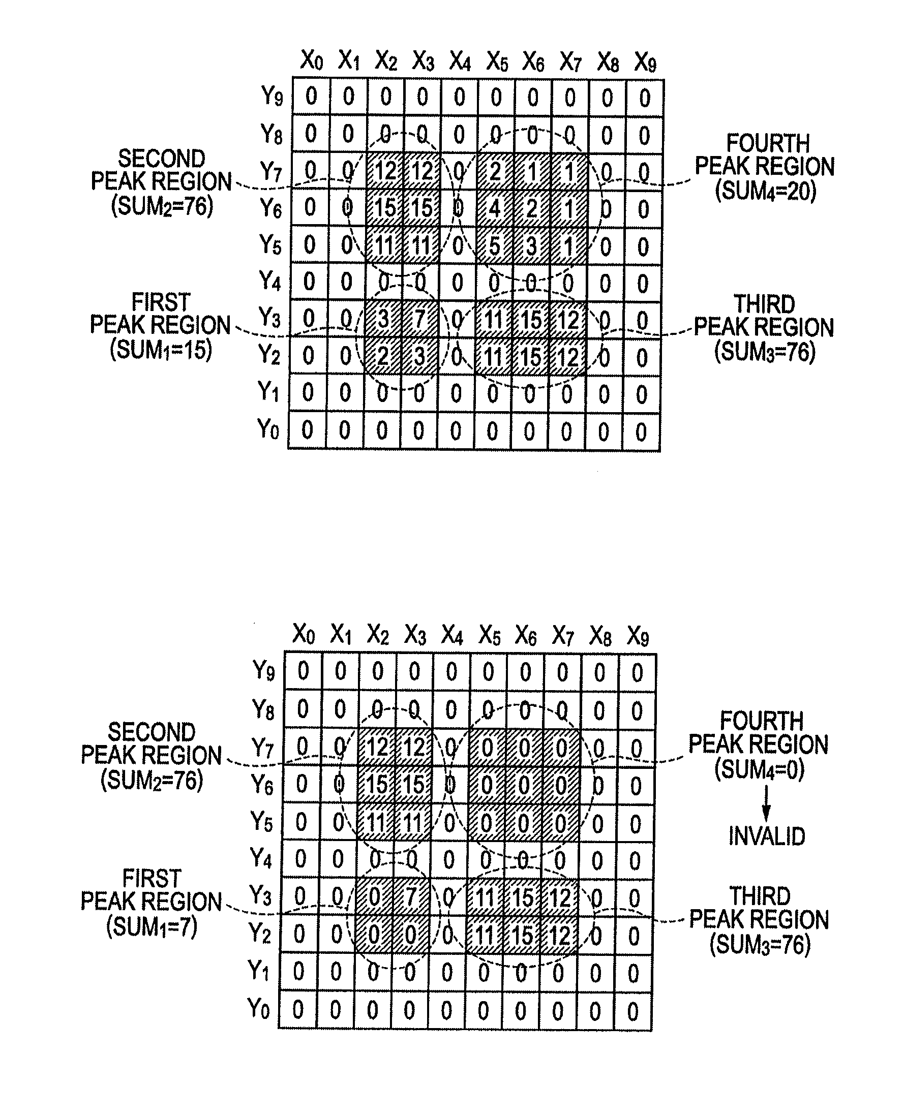
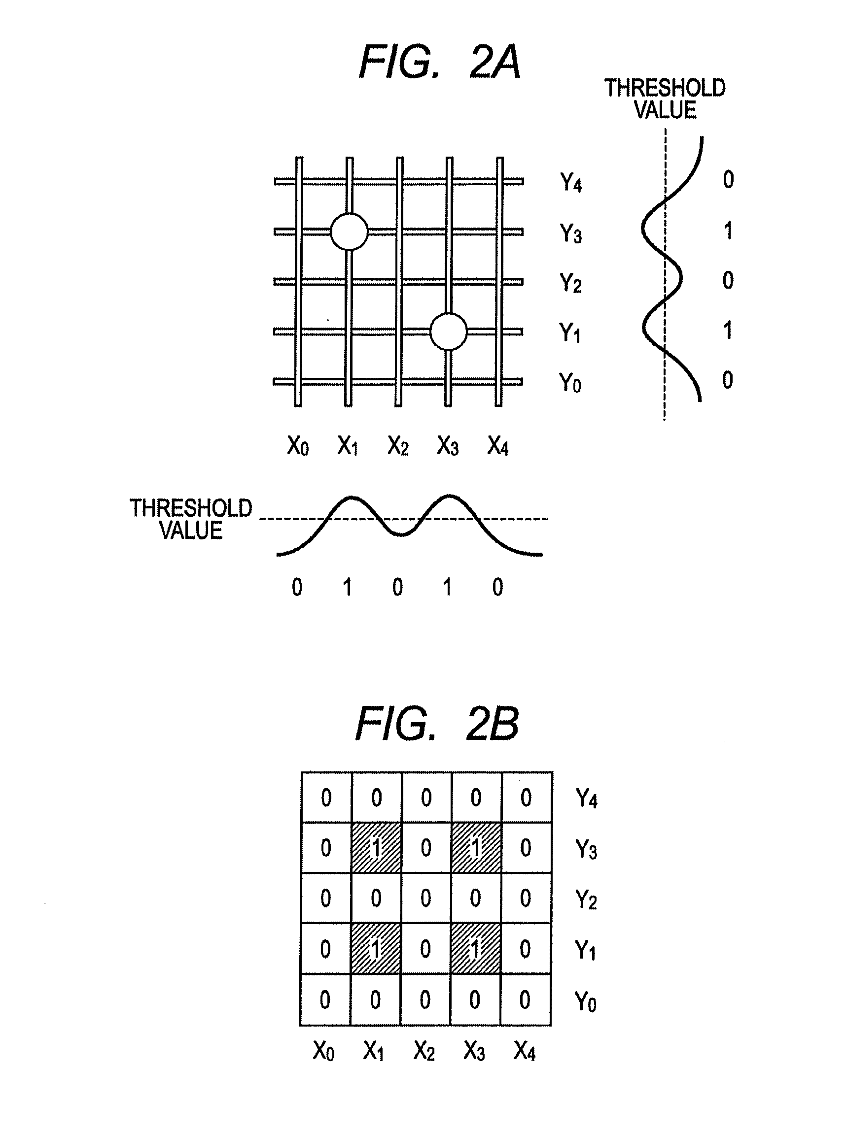
[0024]First, a case in which the coordinates of a detection target are determined on the basis of a sensor output value from each of a plurality of electrodes and a case in which the coordinates of the detection target are determined on the basis of a sensor output value at an intersection point between the plurality of electrodes will be described. In an embodiment, the sensor output value detected from the electrode may be changed by the touch of the detection target to an operation surface. For example, in a capacitance type, the sensor output value may be a digitized value of a capacitance variation which is changed by the touch of the detection target.

[0025]When the coordinates of the detection target are determined on the basis of the sensor output value from each of the plurality of electrodes (see FIG. 2), a combination of the electrodes from which a sensor output value equal to or greater than a predetermined value (first threshold value) is output is specified. In the stru...


PUM


Abstract

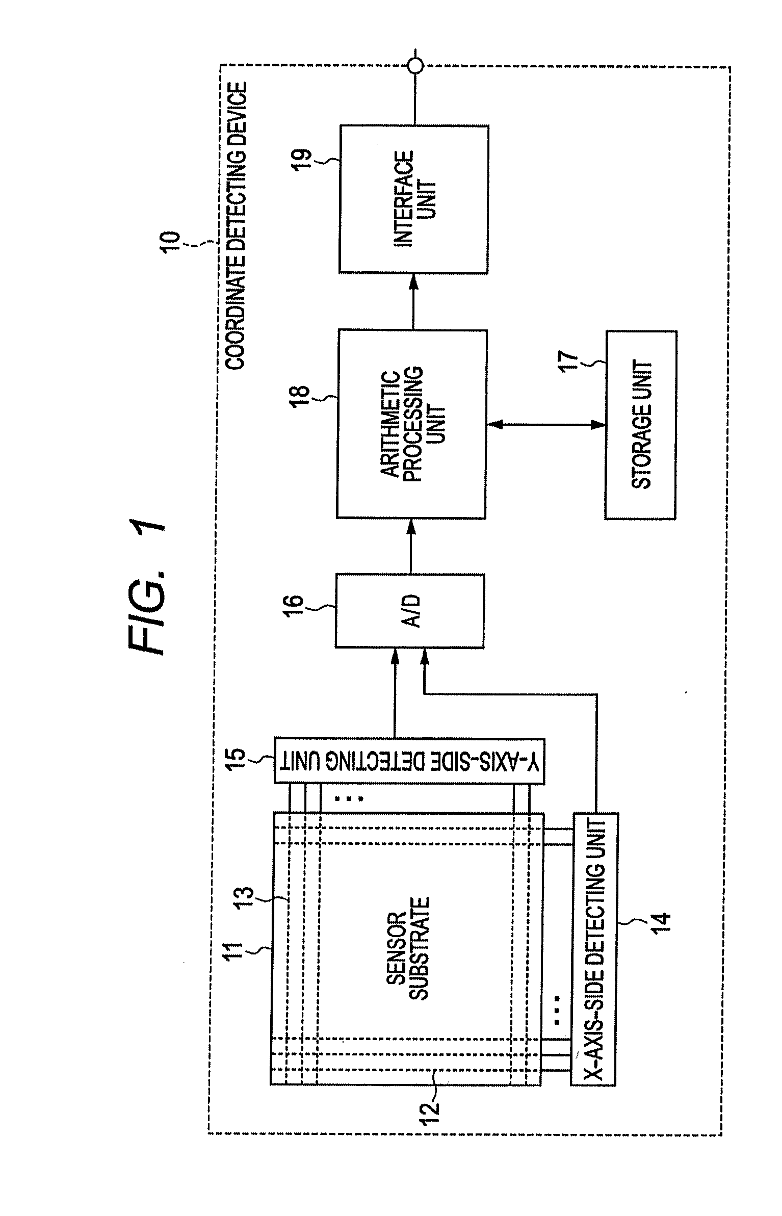
A coordinate detecting device includes a plurality of first and second electrodes, a detecting unit for scanning the first and second electrodes to detect sensor output values of the first and second electrodes, and an arithmetic processing unit for performing an arithmetic process on the basis of the detected sensor output values. When there are a plurality of peak regions in which the sensor output values of both the first and second electrodes are equal to or greater than a first threshold value, the detecting unit detects the sensor output values at intersection points between the first and second electrodes in the peak regions. The arithmetic processing unit calculates the coordinates of a detection target on the basis of the sensor output values at the intersection points between the first and second electrodes in the peak regions and the coordinates of the first and second electrodes in the peak regions.

Description

CLAIM OF PRIORITY[0001]This application claims benefit of Japanese Patent Application No. 2011-144102 filed on Jun. 29, 2011, which is hereby incorporated by reference in its entirety.BACKGROUND[0002]1. Field of the Disclosure[0003]The present disclosure relates to a coordinate detecting device, and more particularly, to a coordinate detecting device related to an operation on a screen.[0004]2. Description of the Related Art[0005]In recent years, a device including a coordinate detecting device which specifies a position where a finger touches to operate an electronic apparatus has been actively developed in electronic apparatuses, such as a computer, a mobile phone terminal, and a PDA (Personal Digital Assistant).[0006]For example, as the device that includes the coordinate detecting device, there is a pointing device (coordinate input device), which is called a pad, a touch pad, or a track pad, provided in the computer. The coordinate input device is incorporated into a portable n...

Claims


Application Information

Patent Timeline
Patent Type & Authority Applications(United States)
IPC IPC(8): G06F3/041
CPCG06F3/0418G06F3/047G06F3/044G06F3/04186G06F3/0446
Inventor HATANO, NAOYUKI
Owner ALPS ALPINE CO LTD
Learn More