
Sequence allocating method and sequence allocating apparatus

a sequence allocating and sequence technology, applied in the field of sequence allocating methods and sequence allocating apparatuses, can solve the problems of increasing processing delays, retransmission errors, and retransmission, and achieve the effect of reducing the amount of calculation and circuit scal

Active Publication Date: 2013-01-03
PANASONIC HLDG CORP
View PDF4 Cites 0 Cited by
  • Summary
  • Abstract
  • Description
  • Claims
  • Application Information

AI Technical Summary

Benefits of technology

This approach reduces the computational burden and circuit complexity on the receiving side while maintaining optimal auto-correlation and cross-correlation characteristics, thereby improving detection efficiency and reducing processing delays.

Problems solved by technology

A random access burst (hereinafter, “RA burst”) transmitted in a random access region (hereinafter, “RA slot”), unlike other scheduled channels, results in reception errors and retransmission due to collision between signature sequences (situation in which a plurality of UEs transmit the same signature sequence using the same RA slot) or interference between signature sequences.
Collision of RA bursts or the occurrence of reception errors increases processing delays in the acquisition of uplink transmission timing synchronization including RA bursts and processing of association request to the BS.

Method used


Image

  • Sequence allocating method and sequence allocating apparatus
  • Sequence allocating method and sequence allocating apparatus
  • Sequence allocating method and sequence allocating apparatus

Examples


embodiment 1

[0032]First, a Zadoff-Chu sequence will be shown using equations. A Zadoff-Chu sequence having a sequence length N is expressed by equation 1 when N is an even number and expressed by equation 2 when N is an odd number.

(Equation1)cr(k)=exp{-j2πrN(k22+qk)}[1](Equation2)cr(k)=exp{-j2πrN(k(k+1)2+qk)}[2]

where k=0, 1, 2, . . . , N−1, “q” is an arbitrary integer and “r” is a sequence number (sequence index). r is coprime to N and is a positive integer smaller than N.

[0033]Next, a GCL sequence will be shown using equations. A GCL sequence having a sequence length N is expressed by equation 3 when N is an even number and expressed by equation 4 when N is an odd number.

(Equation3)cr,m(k)=exp{-j2πrN(k22+qk)}bi(kmodm)[3](Equation4)cr,m(k)=exp{-j2πrN(k(k+1)2+qk)}bi(kmodm)[4]

where k=0, 1, 2, . . . , N−1, “q” is an arbitrary integer, “r” is coprime to N and is a positive integer smaller than N, “bi(k mod m)” is an arbitrary complex number and “i”=0, 1, . . . , m−1. Furthermore, when the cross-cor...

embodiment 2

[0086]A case has been explained in Embodiment 1 where preamble sequences are generated and detected in the time domain, and a case will be explained in Embodiment 2 of the present invention where preamble sequences are generated and detected in the frequency domain.

[0087]The UE configuration according to Embodiment 2 of the present invention is similar to that of Embodiment 1 shown in FIG. 3, and will therefore be explained using FIG. 3.

[0088]FIG. 10 is a block diagram showing a configuration of RA burst generating section 162 according to Embodiment 2 of the present invention. In this figure, RA burst generating section 162 is provided with ZC sequence generation section 171, IDFT section 172 and CP adding section 173.

[0089]ZC sequence generation section 171 generates a Zadoff-Chu sequence in the frequency domain and outputs respective coefficients (symbols) of the Zadoff-Chu sequence generated to predetermined subcarriers of IDFT section 172.

[0090]IDFT section 172 applies inverse ...

embodiment 3

[0114]A case will be explained in Embodiment 3 of the present invention where preamble sequences are generated in the time domain and the preamble sequences are detected in the frequency domain.

[0115]Since the configuration of a UE according to Embodiment 3 of the present invention is similar to the configuration of Embodiment 1 shown in FIG. 3, FIG. 3 will be used for explanations thereof.

[0116]FIG. 14 is a block diagram showing a configuration of RA burst generating section 162 according to Embodiment 3 of the present invention. FIG. 14 is different from FIG. 10 in that N-point DFT section 202 is added and ZC sequence generation section 171 is changed to ZC sequence generation section 201.

[0117]ZC sequence generation section 201 generates a Zadoff-Chu sequence in the time domain and outputs each coefficient (symbol) of the generated Zadoff-Chu sequence to N-point DFT section 202.

[0118]N-point DFT section 202 has the same number of points as the sequence length N of the Zadoff-Chu ...


PUM


Abstract

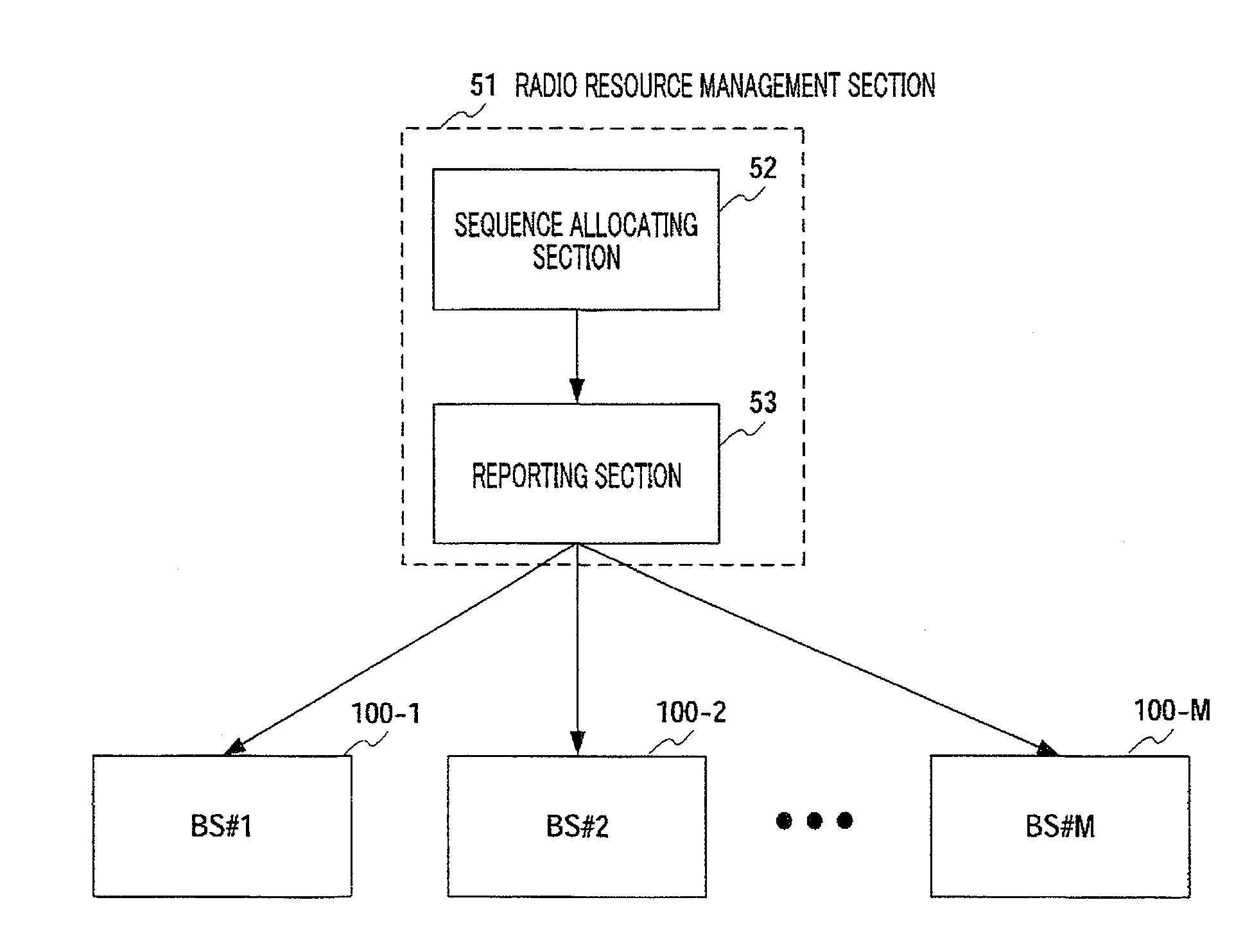
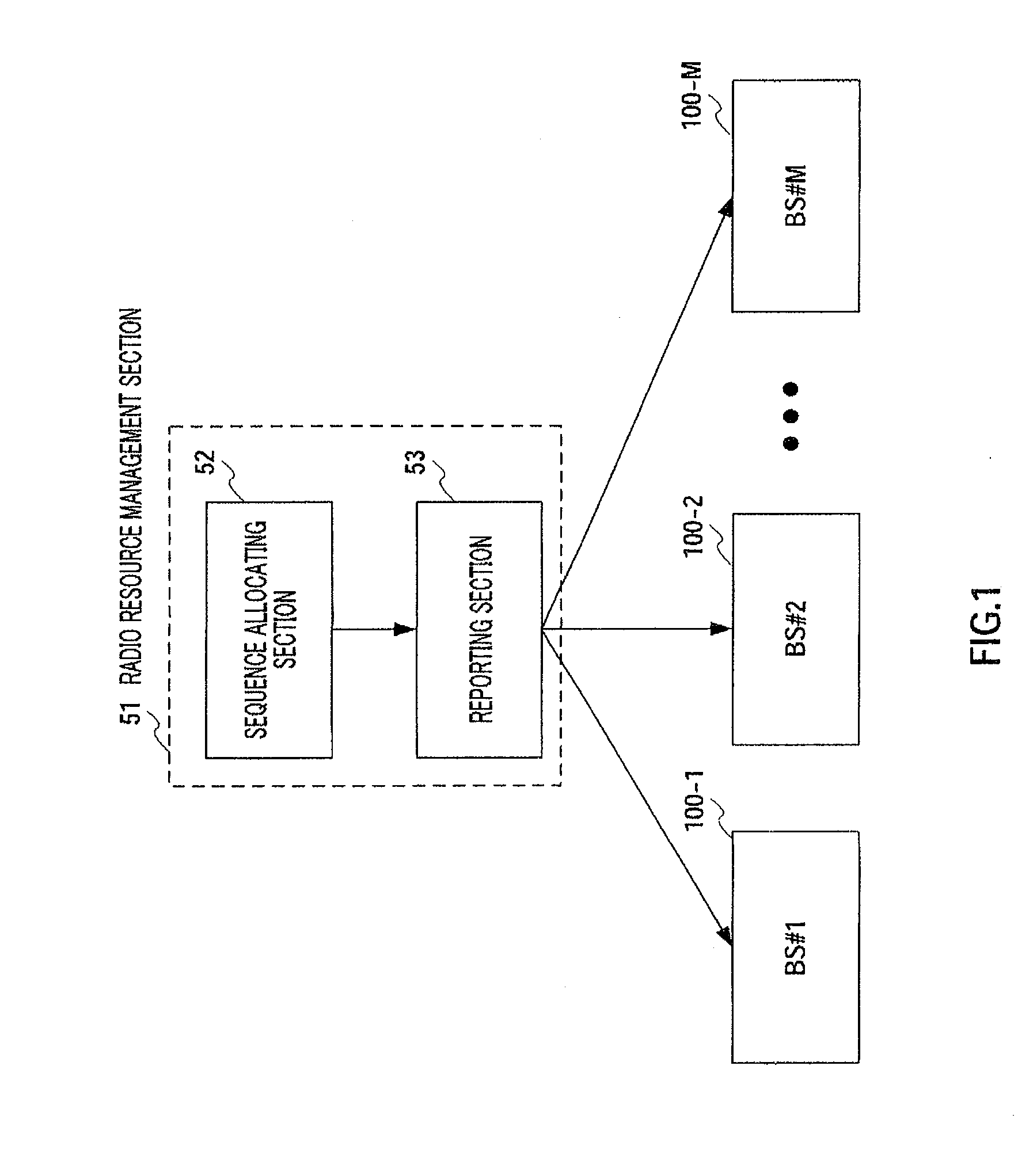
A sequence allocating method and apparatus wherein in a system where a plurality of different Zadoff-Chu sequences or GCL sequences are allocated to a single cell, the arithmetic amount and circuit scale of a correlating circuit at a receiving end can be reduced. In ST201, a counter (a) and a number (p) of current sequence allocations are initialized, and in ST202, it is determined whether the number (p) of current sequence allocations is coincident with a number (K) of allocations to one cell. In ST203, it is determined whether the number (K) of allocations to the one cell is odd or even. If K is even, in ST204-ST206, sequence numbers (r=a and r=N−a), which are not currently allocated, are combined and then allocated. If K is odd, in ST207-ST212, for sequences that cannot be paired, one of sequence numbers (r=a and r=N−a), which are not currently allocated, is allocated.

Description

TECHNICAL FIELD[0001]The present invention relates to a sequence allocation method and a sequence allocating apparatus for allocating a Zadoff-Chu sequence or GCL sequence to a cell.BACKGROUND ART[0002]Mobile communication systems represented by a cellular communication system or wireless radio LAN (i.e. local area network) systems are provided with a random access region in their transmission regions. This random access region is provided in an uplink transmission region when a terminal station (hereinafter, “UE”) sends a connection request to a base station (hereinafter, “UE”) sends a connection request to a base station (hereinafter, “BS”) for the first time, or when a UE makes a new band allocation request in a centralized control system where a BS or the like allocates transmission times and transmission bands to UEs. The base station may be referred to as an “access point” or “Node B.”[0003]Furthermore, in a system using TDMA (i.e., time division multiple access) such as the 3...

Claims


Application Information

Patent Timeline
Patent Type & Authority Applications(United States)
IPC IPC(8): H04W72/00H04W74/08H04B1/707H04J13/00H04J13/10H04J13/16H04J13/22
CPCH04B2201/70702H04J13/0062H04J13/102H04W72/0453H04L27/2613H04W72/04H04W72/0446H04J13/22H04W74/0833H04J13/16H04J11/00H04W74/00H04W74/08H04B1/707H04L23/02H04W74/0875H04B1/7083H04B2201/70713H04L5/0048
Inventor IMAMURA, DAICHIIWAI, TAKASHIINOGAI, KAZUNORIFUTAGI, SADAKIMATSUMOTO, ATSUSHI
Owner PANASONIC HLDG CORP
Learn More