
Fitting confirmation construction for connectors

a technology of fitting confirmation and connectors, applied in the direction of electrical apparatus, connection, coupling device connection, etc., can solve the problems of difficult visual confirmation of whether or not both the connectors b>1/b>′, b>18/b> are properly fitted together, and the cost involved becomes high

Active Publication Date: 2013-01-03
YAZAKI CORP
View PDF1 Cites 8 Cited by
  • Summary
  • Abstract
  • Description
  • Claims
  • Application Information

AI Technical Summary

Benefits of technology

The present invention provides a fitting confirmation construction that allows for easy and visual confirmation of proper connectors fitting connection, especially in situations where the connectors are not perfectly aligned. The invention is simple and low-cost. It utilizes a lock arm and an operation plate portion that can be visually confirmed through a confirmation opening in the housing of one connector. The invention provides a reliable and cost-effective solution for ensuring proper fitting connection of connectors.

Problems solved by technology

Thus, like an example shown in FIG. 14, whether or not both the connectors 1′, 18 are fitted together properly has to be confirmed visually from a direction indicated by arrow E, that is, from the rear in an inserting direction of the flat-circuit-element-side connector 1′, causing a problem that the visual confirmation on whether or not both the connectors 1′, 18 are fitted together properly is difficult.
In addition, the way of confirming the proper connectors fitting connection by visually confirming the movement of the marked arm as described in JP-A-5-343133 or the differently colored housing as described in JP-A-2004-363044 has caused a problem that costs involved become high.

Method used


Image

  • Fitting confirmation construction for connectors
  • Fitting confirmation construction for connectors
  • Fitting confirmation construction for connectors

Examples


Embodiment Construction

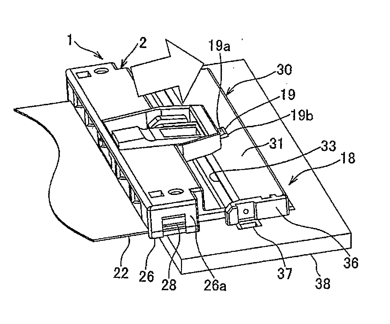
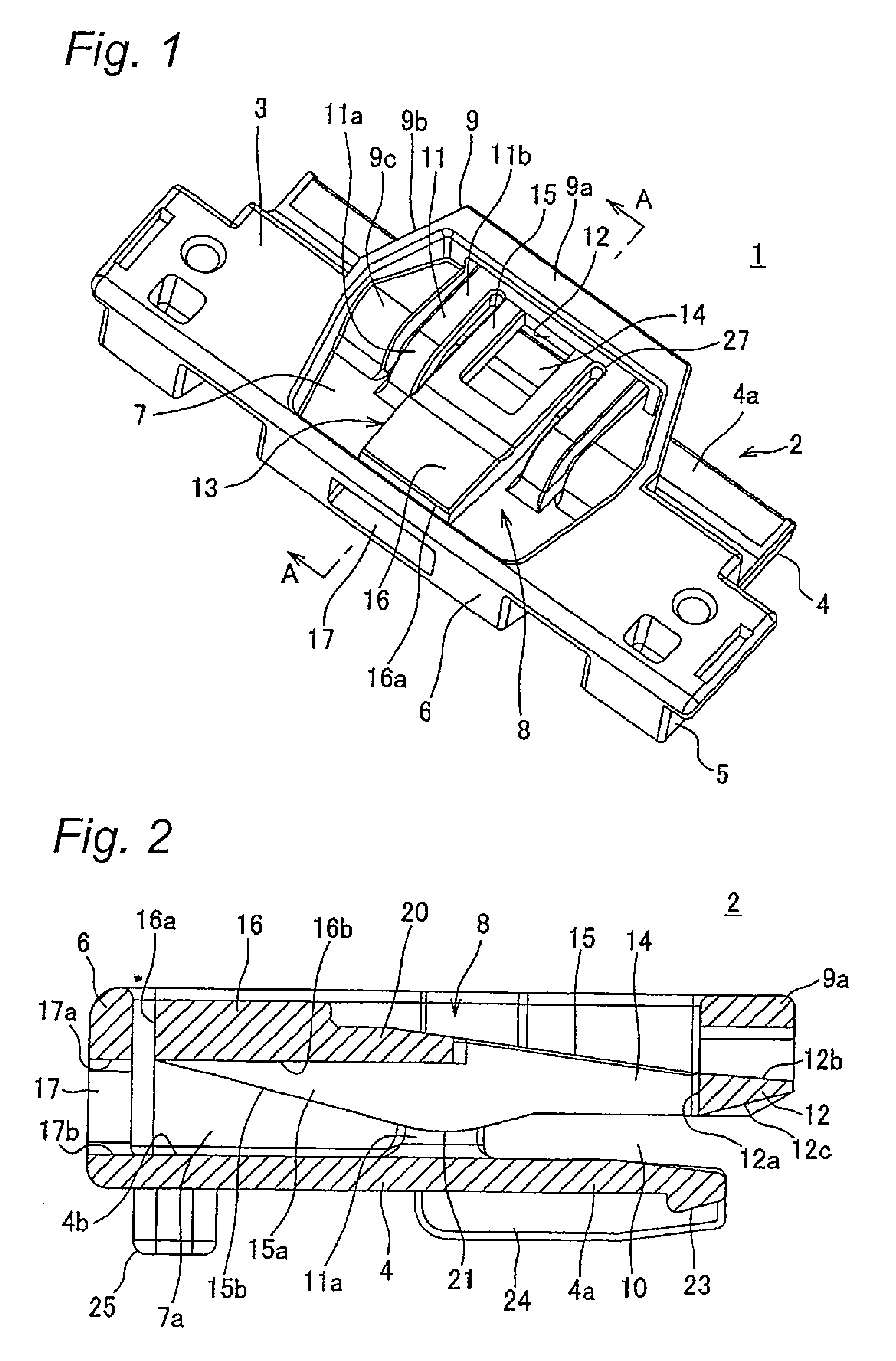
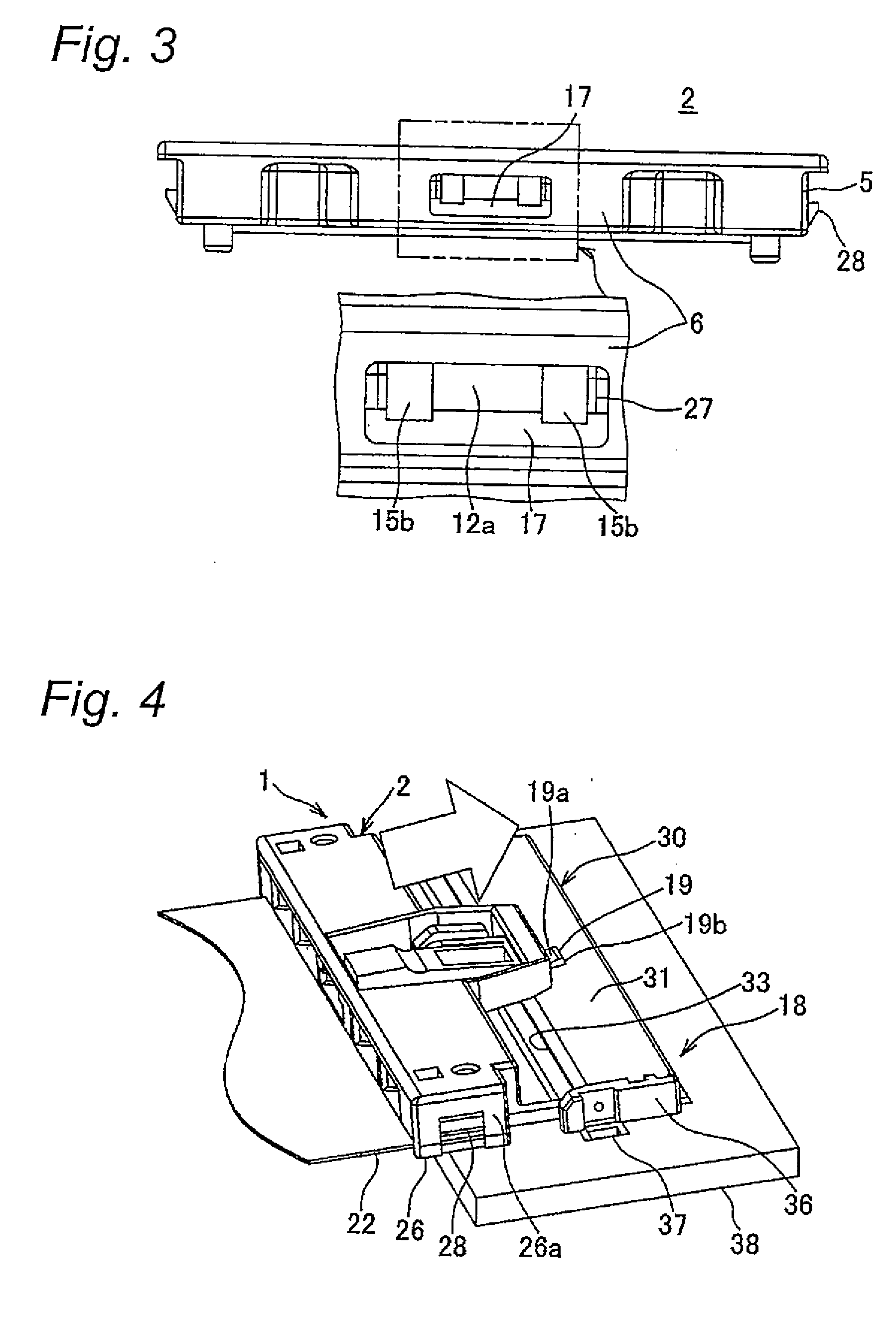
[0042]FIGS. 1 to 11B show an embodiment of a fitting confirmation construction according to the invention.

[0043]FIGS. 1 to 3 show a form of a housing 2, made of insulating resin, of a flat-circuit-element-side connector 1 (a first connector). As shown in FIG. 1, the housing 2 includes a horizontal upper wall 3 having a laterally elongated rectangular shape, a horizontal bottom wall 4 which is situated below the upper wall 3 so as to face the same wall and which is extended longer to the front than the upper wall 3, left and right vertical side walls 5, a vertical rear wall 6, a flexible lock arm 8 which is placed within a substantially rectangular opening portion 7 in the center of the upper wall 3, an arm protection wall 9 which covers a circumference of the lock arm 8, and a flat mating connector insertion space 10 (FIG. 2) which is defined between the lock arm 8 and an front-half projecting portion 4a of the bottom wall 4.

[0044]The lock arm 8 has the same shape as that of the con...


PUM


Abstract

In a fitting confirmation construction, a lock arm is provided in a housing of a first connector. The lock arm includes a lock wall inclined and disposed at a front end of the lock arm in a direction from the first connector toward the second connector; a deflection space formed at a rear of the lock wall in the direction; and an operation plate disposed on the deflection space. A confirmation opening is provided in a rear wall of the housing, and has a height equal to a height of the deflection space. A lock projection is provided on a second connector to be brought into engagement with the lock wall. A rear end face of the operation plate is exposed to a rear outside of the housing of the first connector through the confirmation opening, only in a state where the lock arm is deflected.

Description

CROSS REFERENCE TO RELATED APPLICATION[0001]This application is a continuation of PCT application No. PCT / JP2011 / 058380, which was filed on Mar. 25, 2011 based on Japanese Patent Application (No. 2010-080953) filed on Mar. 31, 2010, the contents of which are incorporated herein by reference. Also, all the references cited herein are incorporated as a whole.BACKGROUND OF THE INVENTION[0002]1. Technical Field[0003]The present invention is related to a fitting confirmation construction for connectors. The fitting confirmation construction enables the confirmation of whether connectors are fittingly connected together completely or incompletely from the rear by employing a confirmation opening in a connector.[0004]2. Background Art[0005]Conventionally, various types of fitting confirmation constructions have been proposed as ones used in connecting together a connector installed at an end of a flexible flat circuit element to a connector installed at an end of a hard printed circuit boa...

Claims


Application Information

Patent Timeline
IPC IPC(8): H01R13/627
CPCH01R12/79H01R13/641H01R13/6272
Inventor OHYAMA, KOUICHI
Owner YAZAKI CORP
Learn More