Drive device for displacing two linearly moveable components pertaining to a plastic injection moulding machine

a technology of linear moving parts and drive devices, which is applied in the field of drive devices, can solve the problems of high cost of threaded drives or rack-and-pinion drives, and achieve the effects of simple and low-cost construction, less susceptible to wear and simple structur

Inactive Publication Date: 2005-07-05
BOSCH REXROTH AG
View PDF9 Cites 4 Cited by
  • Summary
  • Abstract
  • Description
  • Claims
  • Application Information

AI Technical Summary

Benefits of technology

[0006]The invention is accordingly based on the object of further developing a drive device of the introductory-mentioned features in such a way that it is less susceptible to wear and is of a relatively simple and low-cost construction.
[0010]The displacement distance by which the output element of the electric linear motor or the threaded or rack-and-pinion drive arranged downstream of the rotating electric motor can be moved can be readily made large enough that, the two movable components of the plastics injection-molding machine can be moved completely separately at successive times.
[0011]It is preferred for there to be in the force chain between the output element and a displaceable component a hydraulic gear mechanism with a first piston-cylinder unit, which has a first hydraulic cylinder, bounding a first cylinder chamber, and with a second piston-cylinder unit, which is located closer to the displaceable component in the force chain and has a second hydraulic piston, bounding a second cylinder chamber, the first cylinder chamber and the second cylinder chamber being fluidically connectable to each other. Such a hydraulic gear mechanism provides great flexibility with regard to the arrangement of the electric motor, since the distance between the two piston-cylinder units can be readily bridged by hydraulic lines. What is more, the effective area on the second hydraulic piston can be made slightly larger than on the first hydraulic piston, so that a force transmission is obtained, and the loading of the elements of the force chain that are located upstream of the hydraulic gear mechanism, for example the loading of a threaded drive, can be kept at a low level. The piston-cylinder units are, in particular, double-acting, so that the movable components can be displaced by the electric motor in opposite directions. It is conceivable in principle to form the blocking device for one movable component as a mechanical, positive locking mechanism. If, however, there is a hydraulic gear mechanism in a force chain, it is possible, in a particularly simple way for the blocking device to be a shut-off valve, by which the second cylinder chamber can be shut off with respect to the first cylinder chamber.

Problems solved by technology

A threaded drive or a rack-and-pinion drive is generally quite expensive.

Method used


Image

  • Drive device for displacing two linearly moveable components pertaining to a plastic injection moulding machine
  • Drive device for displacing two linearly moveable components pertaining to a plastic injection moulding machine
  • Drive device for displacing two linearly moveable components pertaining to a plastic injection moulding machine

Examples


Embodiment Construction

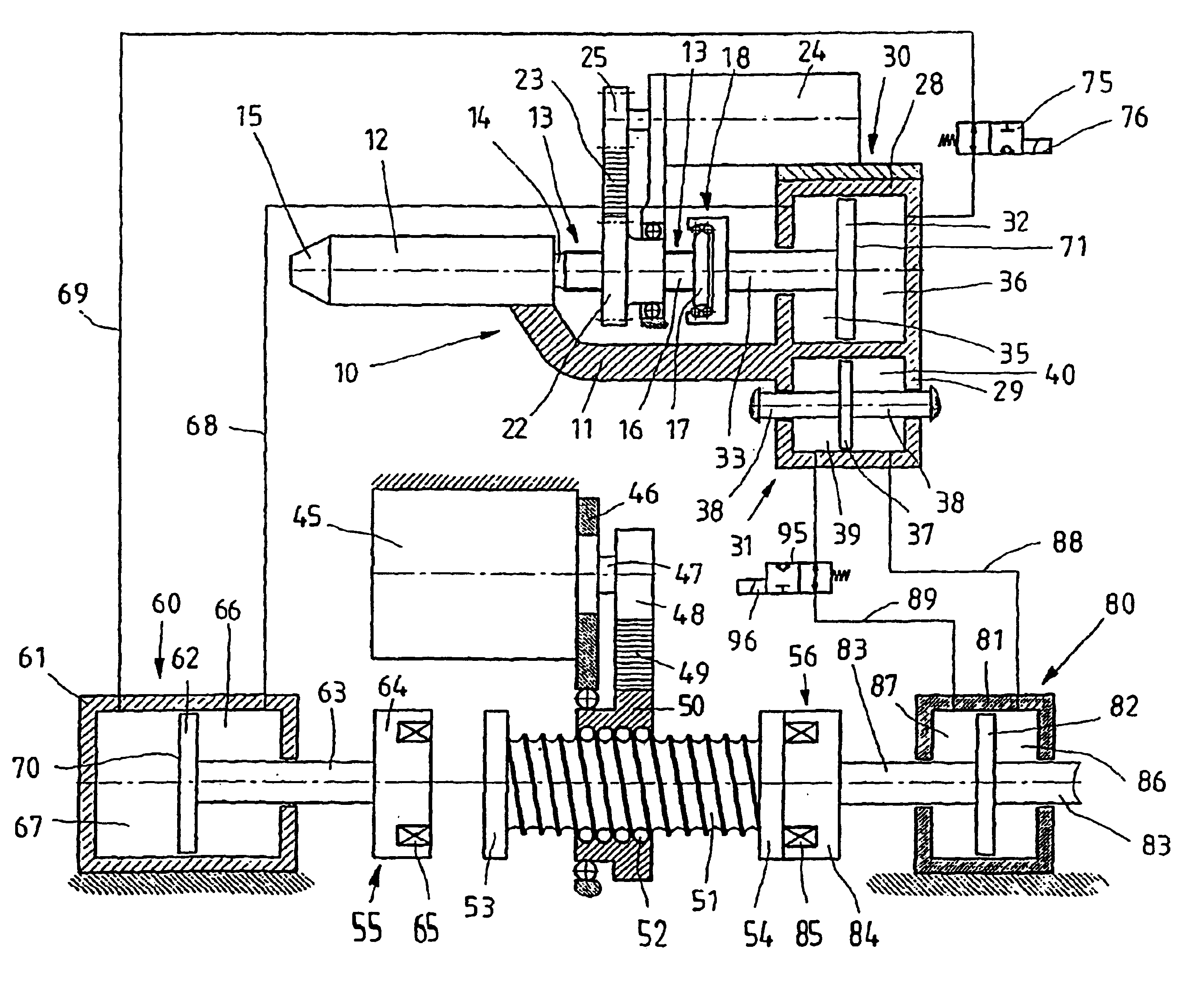
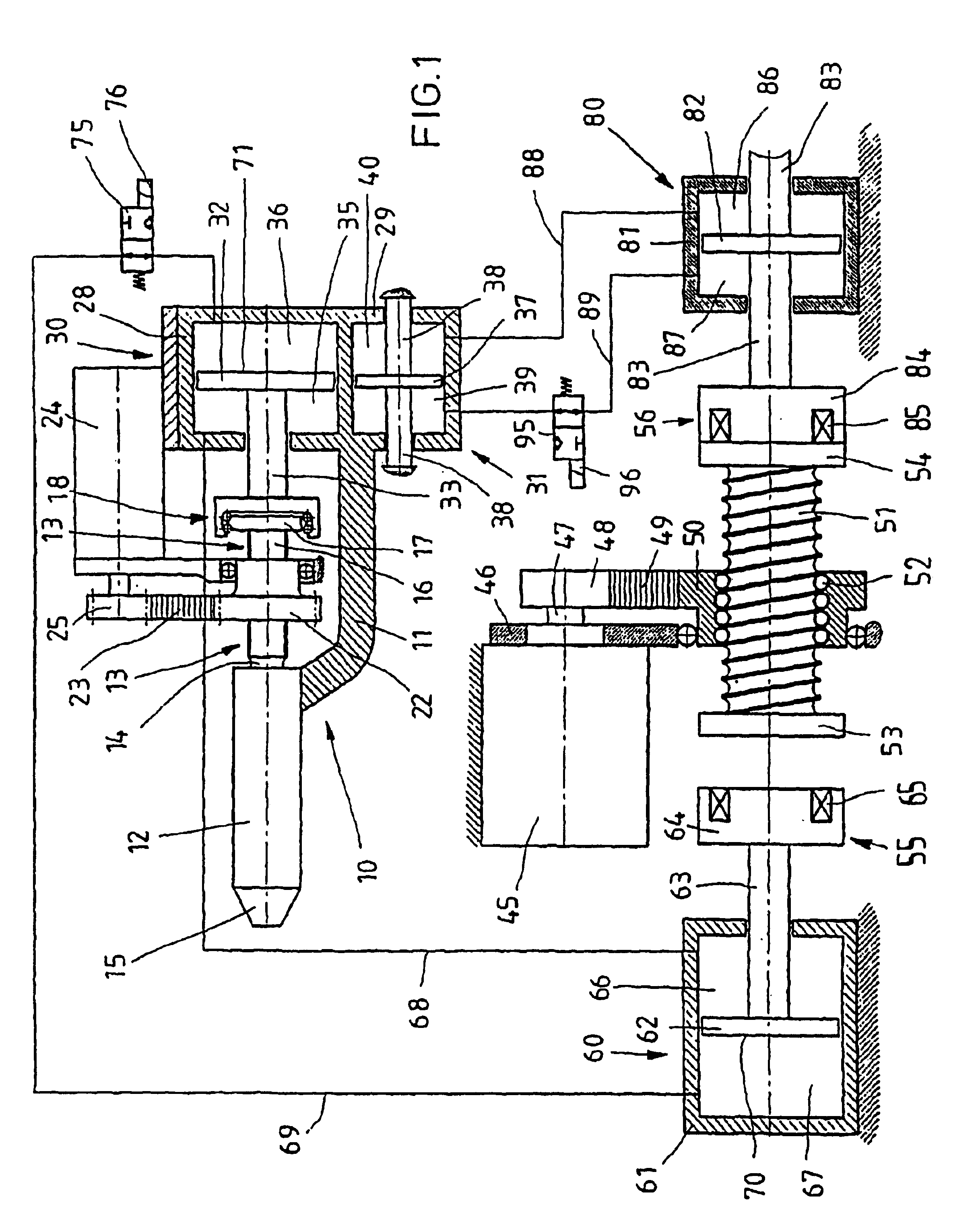
[0018]According to FIG. 1, a plastics injection-molding machine, which is not represented in any more detail in its entirety, has an injection unit 10 with a housing 11, on which a plasticizing cylinder 12 is arranged. Mounted on the housing 11 in a rotatable and axially displaceable manner is an injection mechanism 13, which comprises a screw 14 which is located substantially inside the plasticizing cylinder 12. A conical end of the plasticizing cylinder 12, facing an injection mold not represented, is designed as an injection nozzle 15. Outside the plasticizing cylinder 12, the screw 14 is adjoined by a splined shaft 16, which is fixedly connected to said screw, is provided with axially running splines and slots and at the free end of which a disk 17 is fastened. This disk is part of a ball bearing 18.

[0019]The splined shaft 16 is surrounded by a gear wheel 22, which is rotatably mounted in an axially fixed manner on the housing 11 and engages with splines and slots on its inside ...


PUM

PropertyMeasurementUnit
displacement distanceaaaaaaaaaa
pressureaaaaaaaaaa
movementaaaaaaaaaa

Abstract

A drive device which is intended for displacing two linearly movable components of a plastics injection-molding machine at least partly at successive times, in particular for displacing the injection unit for bringing the injection nozzle into contact with a mold and for displacing the injection mechanism for injecting polymer into the mold. With a known drive device, arranged downstream of an electric rotating motor are two clutches, by which rotational movements are transmitted on the basis of frictional engagement, and with which wear accordingly occurs. Each clutch is followed by a threaded drive, by which the rotational movement of the output element of a clutch is transformed into the linear movement of the machine component to be displaced. To make the known drive device for a plastics injection-molding machine less susceptible to wear and less costly in a first way the threaded drive is arranged between the electric motor and the two clutches and, for displacing the one movable component, the linearly movable drive output element of the threaded drive is able to be moved beyond the displacement distance necessary for displacing the other movable component. In a second way the electric motor is an electric linear motor with a linearly movable drive output element, arranged downstream of which in the force chains are the two clutches, and for displacing the one movable component, the drive output element is movable beyond the displacement distance necessary for displacing the other movable component.

Description

FIELD AND BACKGROUND OF THE INVENTION[0001]The invention relates to a drive device which is intended for displacing two linearly movable components of a plastics injection-molding machine at least partly at successive times, in particular for displacing the injection unit for bringing the injection nozzle into contact with a mold and for displacing the injection mechanism for injecting polymer into the mold.[0002]Such a drive device is known from U.S. Pat. No. 4,540,359. Used there is an electric rotating motor, to move an injection unit including the injection nozzle up to an injection mold and away from the mold again, in order in this way to execute the so-called nozzle forward movement, and to move an injection mechanism including a plasticizing screw axially, for injecting polymer into the injection mold. The two movements take place completely separately at successive times. The electric motor is fastened laterally to the housing of the injection unit, its axis running paralle...

Claims


Application Information

Patent Timeline
Patent Type & Authority Patents(United States)
IPC IPC(8): B29C45/03B29C45/07B29C45/50B29C45/46
CPCB29C45/07B29C45/5008B29C2045/506B29C2045/5068
Inventor DANTLGRABER, JORG
Owner BOSCH REXROTH AG
Why Eureka
Try Eureka