Constructive arrangement for a hermetic refrigeration compressor

a construction arrangement and compressor technology, applied in the direction of positive displacement liquid engines, lighting and heating apparatus, room acoustics, etc., can solve the problems of continuous degradation in compressor efficiency, achieve the effect of facilitating heat exchange, dissipating heat, and attenuating both the noise and the pulsation of discharge gas

Inactive Publication Date: 2014-10-14
EMBRACO IND DE COMPRESSORES E SOLUCOES EM REFRIGERACAO LTDA
View PDF10 Cites 3 Cited by
  • Summary
  • Abstract
  • Description
  • Claims
  • Application Information

AI Technical Summary

Benefits of technology

[0007]It is an object of the present invention to provide a constructive arrangement for a hermetic refrigeration compressor presenting a head external to the shell contour, which prevents the refrigerant fluid from leaking to the exterior of the compressor shell, improves heat dissipation in the head region and presents a simple and low cost construction. It is another object of the present invention to provide an arrangement as cited above, which improves the noise attenuation in the compressors presenting the head external to the contour of the shell portion.
[0010]The constructive arrangement of the compressor of the present invention further allows obtaining an additional discharge chamber which facilitates heat exchange, through the head wall, between the relatively hot gas of the discharge chamber and the external environment, forming a volume of air which actuates dissipating the heat coming from the discharge chamber.
[0011]According to another aspect of the present invention, the head presents a first discharge chamber and a second discharge chamber in fluid communication through a passage dimensioned in such a way as to attenuate both the noise and the pulsation of the discharge gas, which is desirable in compressors using refrigerant gas CO2 for commercial refrigeration. The present construction further allows increasing the heat exchange between the relatively hot discharge gas and the external environment, reducing overheating of the internal components of the compressor (which improves its reliability), as well as of the gas being drawn (which improves its efficiency).

Problems solved by technology

Such leaks, when they occur, cause a continuous degradation in the compressor efficiency.

Method used


Image

  • Constructive arrangement for a hermetic refrigeration compressor
  • Constructive arrangement for a hermetic refrigeration compressor
  • Constructive arrangement for a hermetic refrigeration compressor

Examples


Embodiment Construction

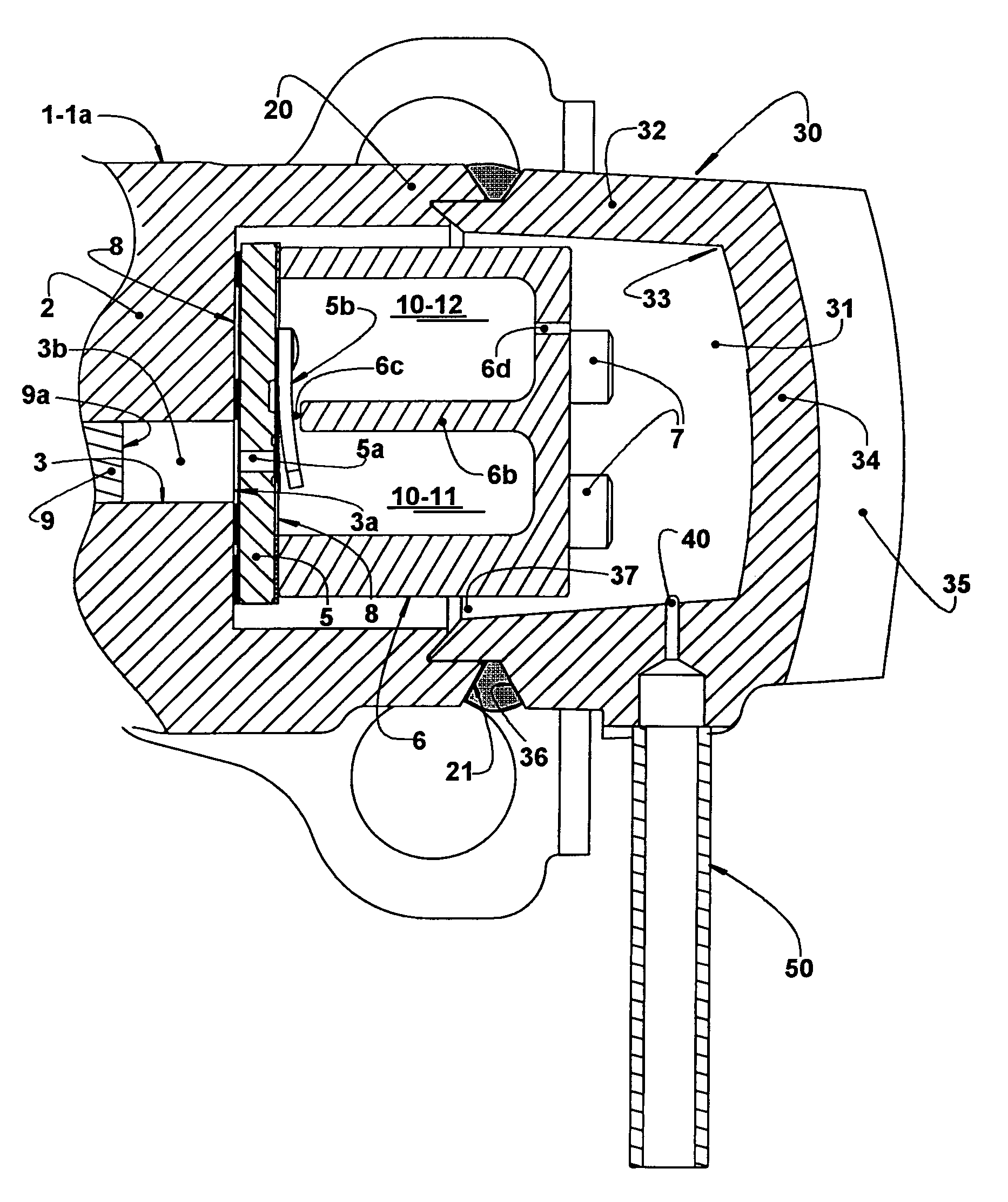
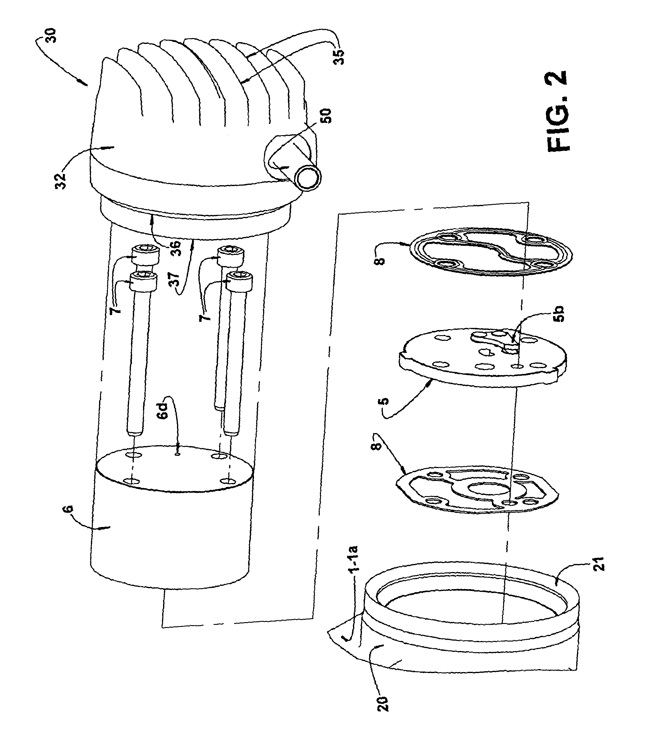
[0016]The present invention will be described for a hermetic refrigeration compressor of the type which comprises a hermetic shell 1 and a motor-compressor assembly, which includes a cylinder block 2 defining, in a single piece, a shell portion 1a of the hermetic shell 1 and a compression cylinder 3.

[0017]The shell portion 1a receives and secures at least one cover 4 which, when positioned inferiorly to the shell portion 1a, generally internally defines an oil reservoir (not illustrated) in the constructions in which the compressor needs lubricant oil to lubricate the relatively moving parts. The shell portion 1a and the cover 4, when affixed to each other, define the hermetic shell 1.

[0018]The compression cylinder 3 presents an end 3a opened to the exterior of the hermetic shell 1 and closed by a valve plate 5 provided with a suction orifice (not illustrated) and a discharge orifice 5a, which are respectively and selectively closed by a suction valve (not illustrated) and a dischar...


PUM


Abstract

A hermetic compressor, comprises: a hermetic shell (1); a cylinder block (2) defining, a shell portion (Ia) and a compression cylinder (3) having an end (3a) opened to the exterior of the hermetic shell (1) and closed by a valve plate (5); a head (6) affixed to the cylinder block (2), over the valve plate (5) so as to define, with the latter, at least one discharge chamber (10). The cylinder block (2) incorporates a tubular projection (20) surrounding the valve plate (5) and at least part of the head (6). An outer cover (30) is hermetically affixed to the tubular projection (20) for defining therewith a discharge plenum (31) in fluid communication with the discharge chamber (10), the tubular projection (20) or the outer cover (30) being provided with a refrigerant gas outlet (40) opened to the exterior of the hermetic shell (1).

Description

FIELD OF THE INVENTION[0001]The present invention refers to a constructive arrangement for the discharge of gas in hermetic refrigeration compressors of the type comprising a cylinder block defining a shell portion which is hermetically closed, at one end, by a cover, said shell portion carrying the motor-compressor assembly of the compressor. The motor-compressor assembly presents a piston reciprocating in the interior of a cylinder defined in the cylinder block and which is closed, at one end, by a head, inside which is defined a discharge chamber. This compressor construction is, for example, of the type used in refrigeration systems using a refrigerant fluid usually containing carbon, such as CO2, in its composition.BACKGROUND OF THE INVENTION[0002]Refrigeration systems that operate with a refrigerant fluid having carbon, such as CO2 in its composition, present operational pressures higher than those obtained with other refrigerant fluids, requiring stronger compressors.[0003]In...

Claims


Application Information

Patent Timeline
Patent Type & Authority Patents(United States)
IPC IPC(8): F04B39/00F04B39/06F04B39/12F25B1/02
CPCF04B39/0061F25B1/02F04B39/066F04B39/122F25B2309/061Y10S181/403
Inventor MOREIRA, EMERSONFAGOTTI, FABIANWEBER, GUSTAVO CARDOSOPEREIRA, MILTON WETZELMACIEL, RICARDO ALEXANDRE
Owner EMBRACO IND DE COMPRESSORES E SOLUCOES EM REFRIGERACAO LTDA
Why Eureka
Try Eureka