Method of manufacturing noise attenuating flexible cutting line for use in rotary vegetation trimmers

a cutting line and flexible technology, applied in the direction of spinnerette packs, transportation and packaging, melt spinning methods, etc., can solve the problems of increasing the need for a noise attenuating cutting line, increasing the noise attenuation characteristics of such lines, and generating considerable noise on projecting nylon lines, so as to enhance the noise attenuation of the line

Inactive Publication Date: 2006-11-23
PROULX MFG
View PDF17 Cites 2 Cited by
  • Summary
  • Abstract
  • Description
  • Claims
  • Application Information

AI Technical Summary

Benefits of technology

[0005] Briefly, the present invention comprises a noise attenuating flexible trimmer line and its method of manufacture. In a first preferred embodiment, the line is comprised of two or more monofilament strands twisted together in a molten state such that upon being cooled in a quench bath, reheated, drawn and cured, the strands are continuously bonded together along their lengths so as to form a single twisted length of cutting line having a plurality of inwardly directed and generally V-shaped troughs terminating in fused seams that extend continuously in a helical disposition about and along the length of the line. By increasing the number of twists per unit length of line, the angle formed by the trough relative to the longitudinal axis of the line is increased and the noise attenuation of the line is enhanced.
[0006] The cross-section of the formed line defines a major diameter wherein the transverse distance across the line is at a maximum and a minor diameter extending through at least one of the troughs in the line wherein the transverse dimension across the line is at a minimum. The major diameter defines the line size. While the individual strands can be extruded in a wide variety of cross-sectional configurations, strands having a circular cross-section are preferred. In the cutting line of the present invention wherein the two individual strands are circular in cross-section prior to bonding, increasing the difference between the major diameter and minor diameter for each line size, further enhances the noise attenuation of the line.
[0007] In an alternate embodiment, the line is comprised of a single monofilament strand, preferably oblately-shaped in cross-section, that is twisted while in a molten state such that, upon being cooled in a quench bath, reheated, drawn and cured, the strand defines a twisted length of cutting line having a slightly out-of-round cross-section that extends continuously in a helical disposition along the entire length of the line. The resultant cutting line, while not as quiet as the line of the prior embodiment, does provide significant noise attenuation as compared to conventional cylindrical line and provides a greater cutting mass for a given major diameter than a line of the first embodiment having the same major diameter.

Problems solved by technology

At these speeds, the projecting nylon lines generate considerable noise which most people find quite objectionable.
However, the high pitch whine given off by the nylon slicing through the air and brush appears to travel further than the lower frequency engine noise and is very noticeable to people not in the immediate proximity of the rotating trimmer head.
As legislative pressure continues to force manufacturers to develop quieter gas-powered engines for these trimmers, the need for a noise attenuating cutting line will only increase.
While efforts to develop suitable cutting lines for rotary trimmers that produce less noise during use have met with some success, the noise attenuating characteristics of such lines still leaves room for improvement.
However, as a result of such modifications, the surface quality and durability of the line is adversely affected and the cost of manufacture is significantly increased.

Method used


Image

  • Method of manufacturing noise attenuating flexible cutting line for use in rotary vegetation trimmers
  • Method of manufacturing noise attenuating flexible cutting line for use in rotary vegetation trimmers
  • Method of manufacturing noise attenuating flexible cutting line for use in rotary vegetation trimmers

Examples


Embodiment Construction

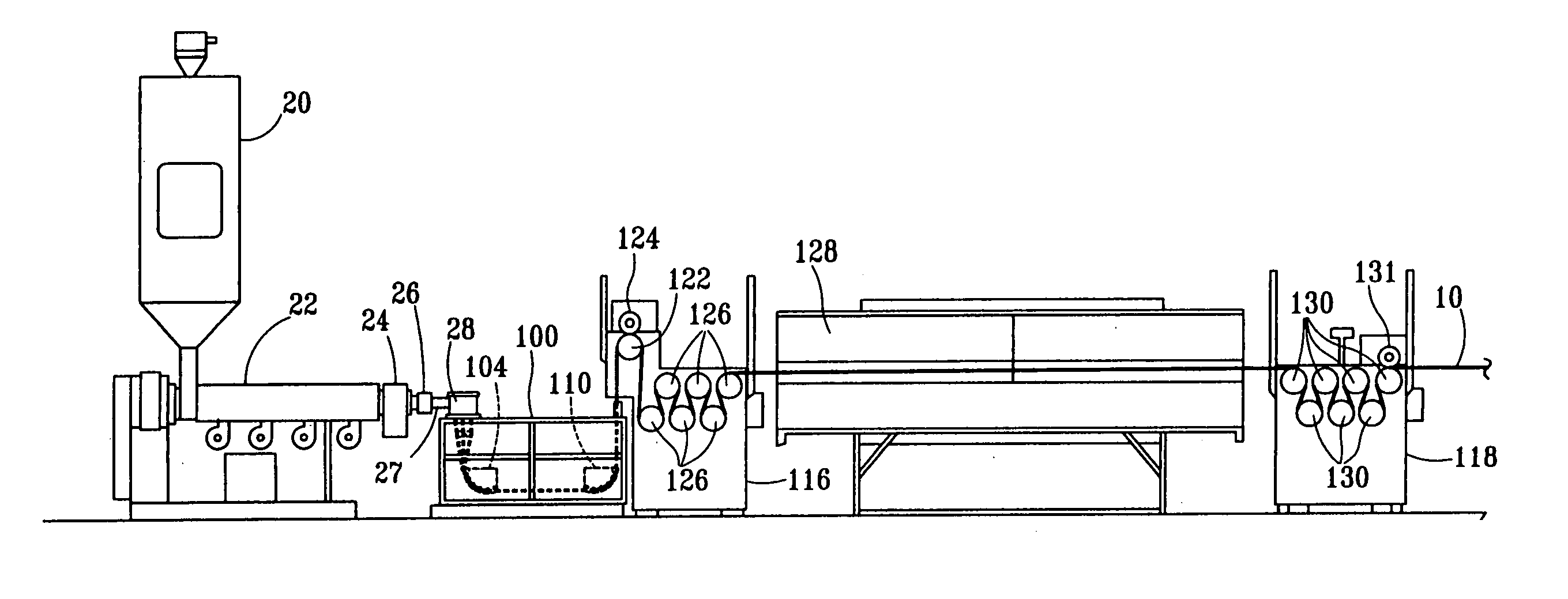
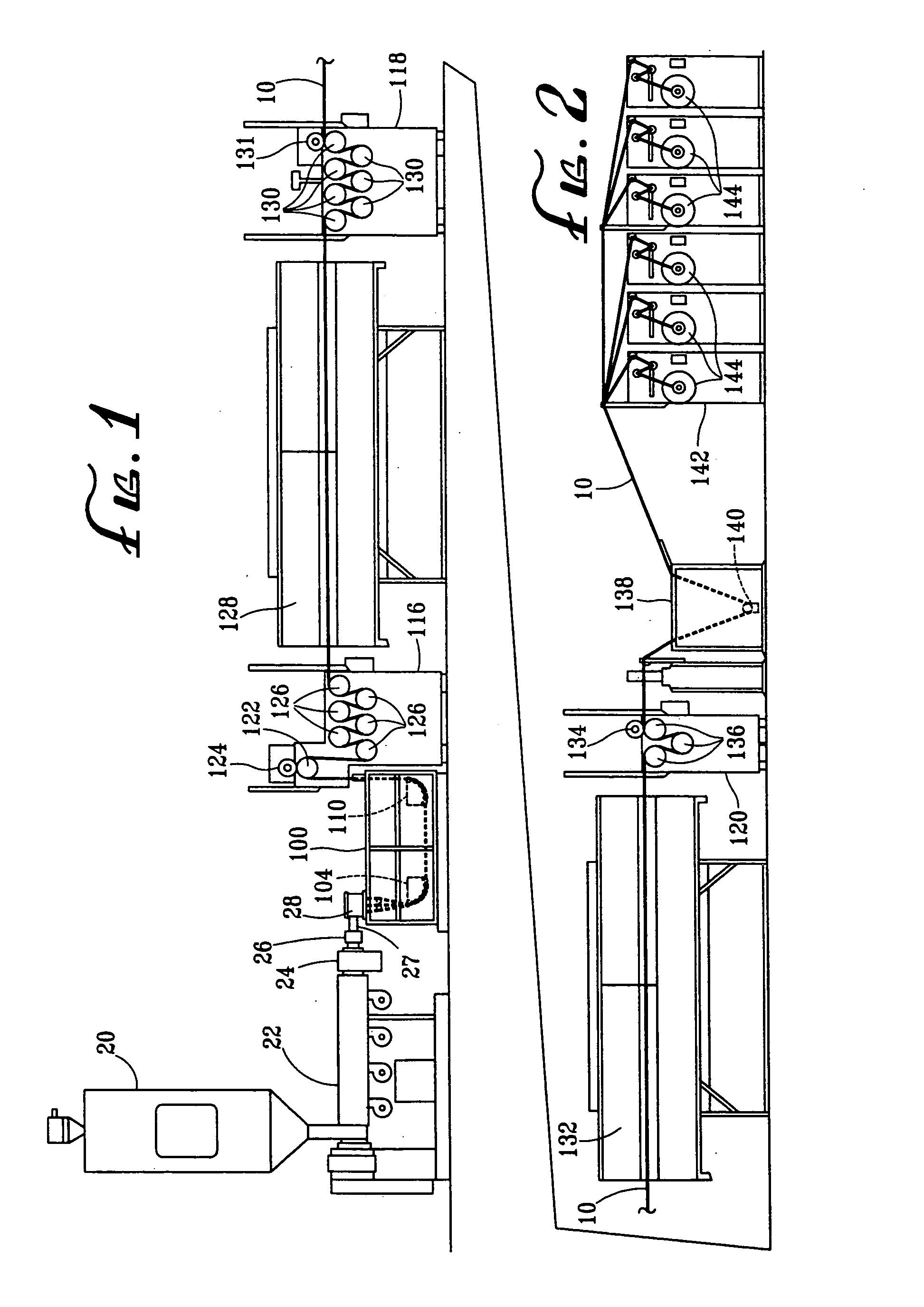
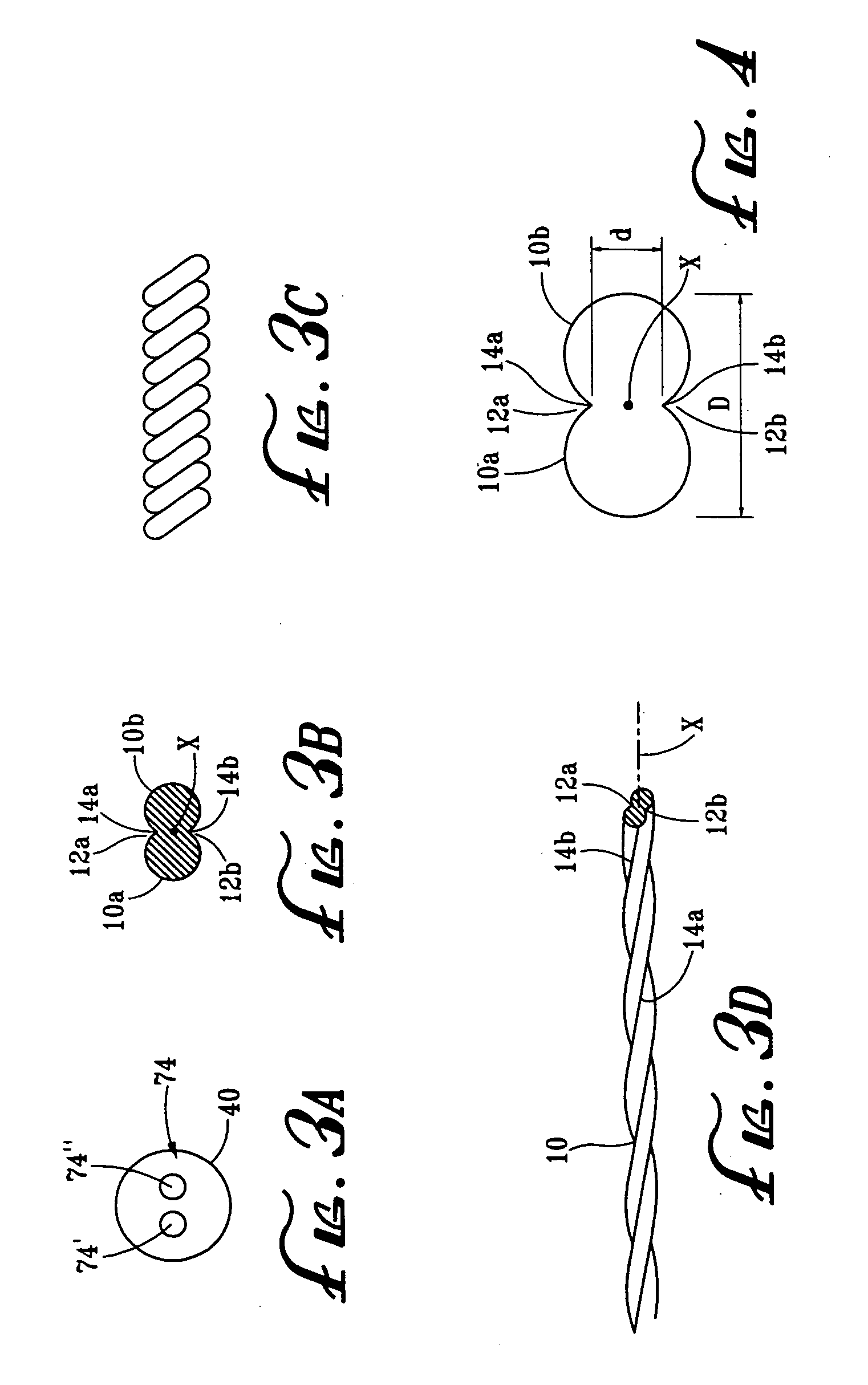
[0046] Referring now in detail to the drawings, the process of the present invention is schematically represented in FIGS. 1 and 2. The result of the process is a noise attenuating monofilament cutting line 10 comprised of two or more monofilament strands continuously bonded together in a twisted configuration. In a preferred embodiment of the cutting line 10 illustrated in FIGS. 3A and 3B, two strands 10a and 10b having cylindrical cross-sections are bonded together in a twisted disposition about a central axis X so as to form a pair of overlapping cylindrical line portions twisted together to define a single length of cutting line 10. Line 10 defines a pair of inwardly directed and generally V-shaped troughs 12a and 12b terminating in fused seams 14a and 14b that extend continuously in helical dispositions about and along the length of the line. It is to be understood that the cutting line of the present invention could be formed with the same process so as to be comprised of more...


PUM

PropertyMeasurementUnit
water temperatureaaaaaaaaaa

Abstract

A process for forming flexible noise attenuating cutting line for use in rotary vegetation trimmers formed of at least two monofilament polymer strands bonded together in a twisted disposition or a single strand twisted about its central axis in which the strand or strands are extruded in a molten disposition through a single die that is rotated during the extruding step either to twist the two strands together about a central longitudinal axis or a single strand about its own longitudinal axis such that upon cooling, stretching and heating, a flexible noise attenuating line is created in a continuous online process.

Description

CROSS-REFERENCE TO RELATED APPLICATIONS [0001] This is a continuation of U.S. patent application Ser. No. 10 / 713,485 filed Nov. 14, 2003, which is a continuation-in-part of U.S. patent application Ser. No. 09 / 943,248, filed Aug. 29, 2001, and entitled “Noise Attenuating Flexible Cutting Line for Use in Rotary Vegetation Trimmers and Method of Manufacture,” now U.S. Pat. No. 6,910,277, issued Jun. 28, 2005.BACKGROUND OF THE INVENTION [0002] The present invention is directed to an improved flexible cutting line for use in rotary trimmers and the method and apparatus employed in the manufacture of such line. Flexible line rotary trimmers are used for cutting vegetation, such as grass and weeds, particularly along walks, fences and flowerbeds and around trees. These devices comprise a motor-driven rotary head which carries one or more lengths of monofilament line mounted on a spool within a housing. Extended end portions of each line project from the spool through guides in the side of ...

Claims


Application Information

Patent Timeline
Patent Type & Authority Applications(United States)
IPC IPC(8): B29C47/12A01D34/416B29C48/30D01D5/18D02G3/44
CPCA01D34/4168A01D34/826B29C47/0014B29C47/0028B29C47/003B29C47/30Y10T428/2973D01D5/08D01D5/18D02G3/402D02G3/44Y10T428/2976D01D4/022B29C48/05B29C48/11B29C48/12B29C48/345B29C48/131
Inventor PROULX, RICHARD A.CONLEY, WILLIAM P.THOMASON, RODGER D.
Owner PROULX MFG
Why Eureka
Try Eureka