
Direct current motor for vehicle

A technology for DC motors and vehicles, applied in vehicle components, DC commutators, electromechanical devices, etc., can solve problems such as insufficient safety, increase the overall size of the motor, and inability to fail the motor, so as to improve safety and reliability, increase Noise attenuation effect, effect of eliminating short-circuit phenomenon

Inactive Publication Date: 2019-06-25
塔玛斯有限公司
View PDF8 Cites 3 Cited by
  • Summary
  • Abstract
  • Description
  • Claims
  • Application Information

AI Technical Summary

Problems solved by technology

In order to solve the above problems, in the past, such as Japanese Patent Laid-Open No. 2001-24545, an elastic body is provided at a predetermined interval between the inner side of the brush holder and the outer side of the brush. In this case, the elastic body can reduce the friction between the brush and the groove. However, the vibration of the above-mentioned elastic body is directly transmitted to the casing of the motor, which still has the problem of greatly inducing noise.
[0011] In addition, in the conventional DC motor, the power supply connector for supplying electricity to the brushes is provided in a manner that can be combined with the support body of the brush holder, but it is not firmly assembled, so the safety is insufficient, and the brushes are not connected. The grip provides a grounding structure. When power is supplied to the brushes, a leakage current may be generated, thereby preventing the failure of the motor. Furthermore, if the leakage current flows through the bearings, a spark (spark) is generated between the narrow bearings, that is, an arc (arc ), bearing electrical corrosion (electrolytic corrosion) that forms grooves on the bearing surface occurs, and thus, the phenomenon that the bearing is easily damaged occurs
[0012] Therefore, in order to ground the motor, a method has been proposed in which an additional ground frame is formed in the bearing cover or a hole is formed in the bearing cover to fix the ground terminal in the hole. However, this method has the following problems. Make the structure of the bearing cover complex to increase the overall size of the motor. Due to the complex structure, it is difficult to install and disassemble the work, thereby increasing the number of overall work steps required to assemble the motor.

Method used


Image

  • Direct current motor for vehicle
  • Direct current motor for vehicle
  • Direct current motor for vehicle

Examples


Embodiment Construction

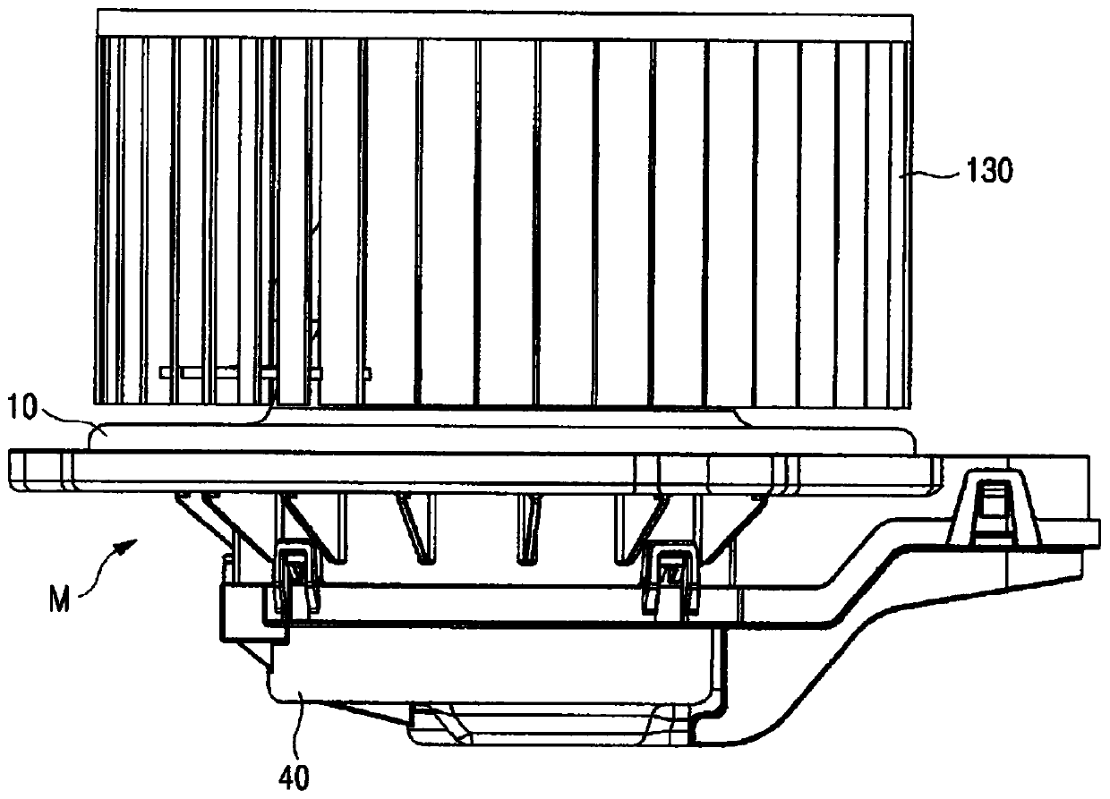
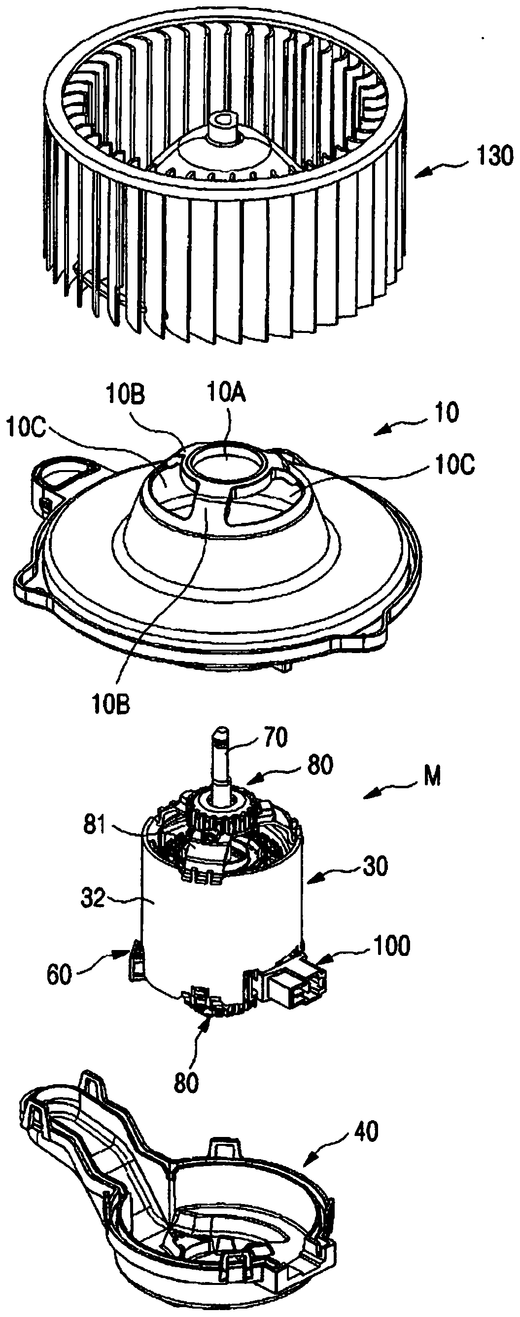
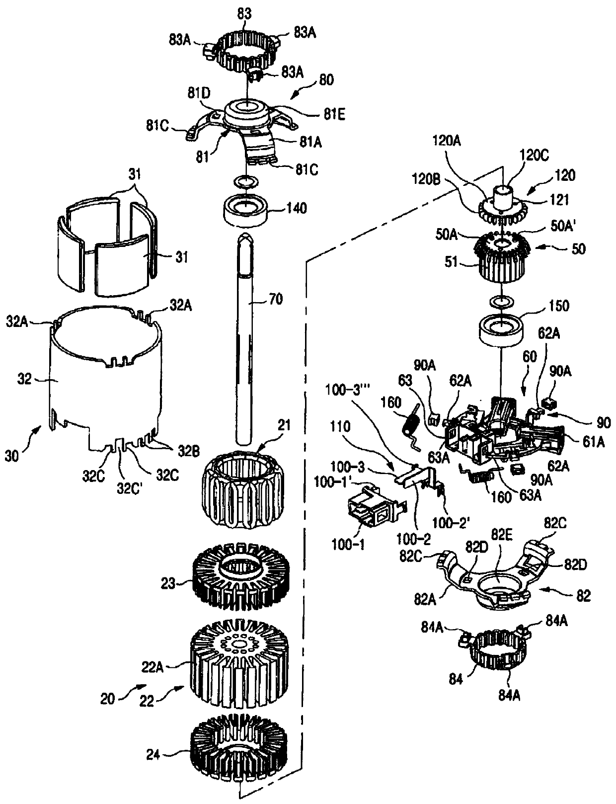
[0052] figure 1 It is a structural diagram of the motor of the present invention, figure 2 For the exploded stereogram, image 3 for with figure 2 The exploded perspective view of the DC motor drive section in Figure 4 It is a combined sectional view of the motor of the present invention.

[0053] refer to Figure 1 to Figure 4 , to illustrate the overall structure of the present invention, the motor M of the embodiment of the present invention includes a cover assembly 10 , an armature assembly 20 , a yoke assembly 30 and a lower housing 40 .

[0054] The DC motor M of the present invention has a lower case 40 combined with the cover assembly 10 and includes a yoke assembly 30 having a plurality of field poles 31 disposed inside the cover assembly 10 . The armature assembly 20 includes: an armature core 22 having a plurality of pole teeth 22A for winding a coil 21 interacting with the above-mentioned field pole 31; Combination of upper and lower parts. The commutato...


PUM


Abstract

A direct current motor for a vehicle, according to the present invention, comprises: a cover assembly (10); a yoke assembly (30) having a lower housing (40) coupled with the cover assembly (10), and aplurality of excitation poles (31) arranged inside the cover assembly (10); an armature assembly (20) comprising an armature core (22) and upper and lower insulators (23, 24), the armature core (22)having a plurality of teeth (22A) around which coils (21) interacting with the excitation poles (31) are wound, and the upper and lower insulators (23, 24) coupling to the upper and lower portions, respectively, of the armature core (22); a commutator (50) installed on the lower side of the armature core (22) and having commutator segments (51) of which the number corresponds to the number of theexcitation poles (31); a brush holder (60) arranged on the inner side of the lower housing (40) and comprising a brush (61) selectively making contact with the commutator (50) according to the rotation of the armature assembly (20); a rotational shaft (70) having the armature core (22) and the commutator (50) coupled thereto so as to rotate therewith; an up / down / left / right vibration and noise dampening buffer means (80) installed on the upper and lower portions, respectively, of the rotational shaft (70); a brush holder left / right vibration and noise dampening buffer means (90) installed on the brush holder (60) so as to be insertedly installed in a yoke cylindrical body (32) constituting the yoke assembly (30); a grounding means (110) comprising a power supply connector (100) coupled to aconnector receiving part (63) formed on a support (62) of the brush holder (60); and an insulating means (120) installed so as to make surface-contact with the upper side of the commutator (50) installed in the center of the support (62) of the brush holder (60).

Description

technical field [0001] The present invention relates to a DC motor for vehicles. More specifically, the present invention relates to a DC motor for vehicles that prevents noise and vibration, has excellent motor efficiency, and is applicable to vehicle air conditioners and the like. Background technique [0002] Generally, there are DC motors disclosed in Patent Laid-Open Publication Nos. 2001-0097340, 2003-0035232, etc., as devices that take in outside air to operate an air-conditioning system that is an automobile air-conditioning device. This type of DC motor uses a blower fan to rotate the air in the atmosphere or the air in the car interior to pass the air around the evaporator, change the high-temperature and humid air into low-temperature dehumidified air, and let it flow into the room to maintain comfortable environment. [0003] In such a DC motor, an armature (armature) is rotatably arranged inside a yoke (yoke) in which magnets are arranged on an inner periphera...

Claims


Application Information

Patent Timeline
Patent Type & Authority Applications(China)
IPC IPC(8): H02K5/24H02K3/34H02K5/14B60H1/00F16F15/02H02K23/00
CPCB60H1/00F16F15/02H02K3/34H02K5/14H02K5/24H02K23/00B60H1/00471F16F15/021H02K3/345
Inventor 蔡桭远崔哲源
Owner 塔玛斯有限公司
Learn More