Antenna Assembly For An Aircraft

an antenna assembly and aircraft technology, applied in the field of aircraft antenna assembly, can solve the problem of air not flowing between the various cavities,

Active Publication Date: 2019-08-08
AIRBUS OPERATIONS GMBH
View PDF0 Cites 3 Cited by
  • Summary
  • Abstract
  • Description
  • Claims
  • Application Information

AI Technical Summary

Benefits of technology

[0005]Aspects of the present invention may provide an antenna assembly for an aircraft which is of simple and low-cost construction, is easy to install and service and has a low weight, and to provide an aircraft which has an antenna assembly of this kind.

Problems solved by technology

If a plurality of cavities is provided, they are separated from one another after the arrangement of the support element on the outer skin section, making it impossible for air to flow between the various cavities.

Method used


Image

  • Antenna Assembly For An Aircraft
  • Antenna Assembly For An Aircraft
  • Antenna Assembly For An Aircraft

Examples


Embodiment Construction

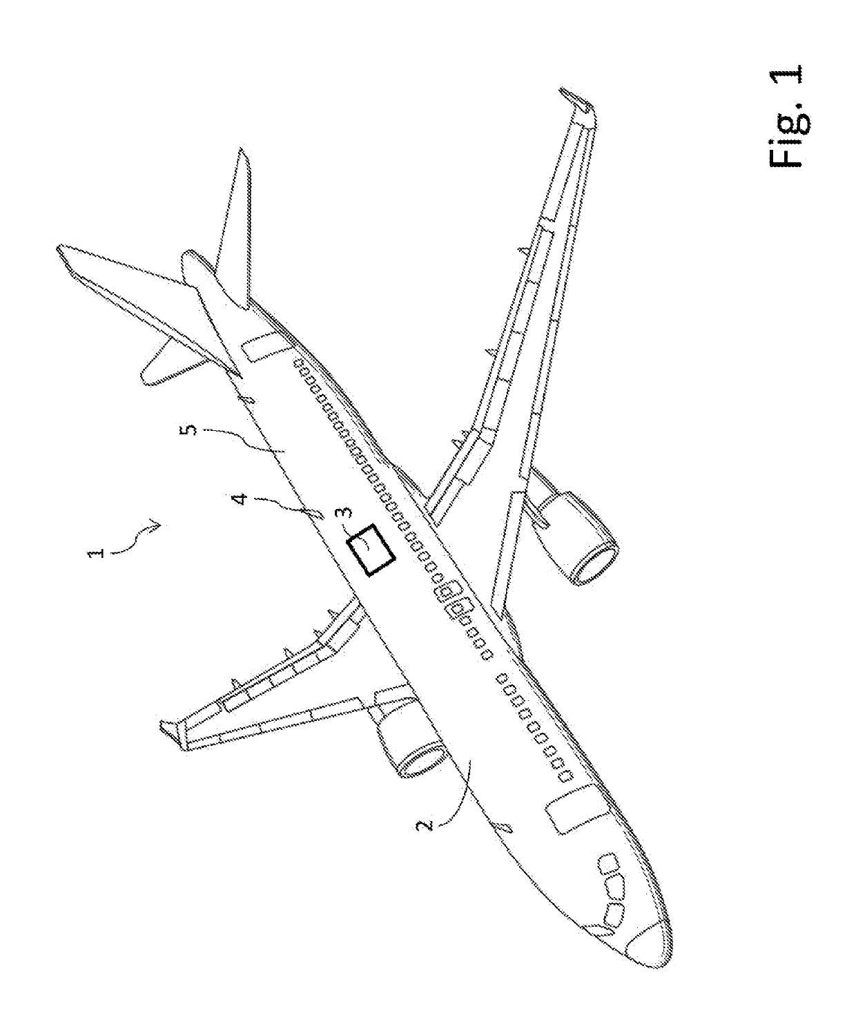
[0037]The aircraft 1 shown in FIG. 1 has a fuselage 2 and an antenna assembly 3 according to an embodiment of the invention. In addition to the antenna assembly 3, conventional blade antennas 4, which are secured externally on the fuselage 2 and project outwards from the fuselage 2, are also shown for purposes of illustration. In contrast, the antenna assembly 3 in the illustrative embodiment shown is configured as a sheet-like and flexible film component and is arranged from the outside on a section of the outer skin 5 of the fuselage 2. In this way, the air resistance of the fuselage 2 is increased insignificantly or not at all by the antenna assembly 3. In FIG. 1, the antenna assembly 3 is arranged on the upper side of the fuselage 2, by way of example. However, it is also possible for the antenna assembly to be situated at any other point on the fuselage 2, e.g. on one side or on the underside or, alternatively, at other points on the aircraft, e.g. a wing or a tailplane.

[0038]T...


PUM


Abstract

An aircraft antenna assembly has a support element having a first and a second surface on opposite sides, an antenna element arranged on or in the support element, and a sealing device. The first surface and the sealing device are configured such that the antenna assembly is arranged on an outer skin section of an aircraft such that the first surface faces the outer skin section, the sealing device is situated between the support element and the outer skin section, and a cavity is defined by the sealing device, the outer skin section and the first surface. The support element or the sealing device y has a flow channel having a first and a second opening at opposite ends, the flow channel connecting the cavity and the environment and opening into the cavity at the first opening and opening into the environment at the second opening.

Description

FIELD OF THE INVENTION[0001]The present application relates to an antenna assembly for an aircraft, which has a support element and at least one antenna element arranged on or in the support element, and to an aircraft having an antenna assembly of this kind.BACKGROUND OF THE INVENTION[0002]Aircraft typically have one or more antennas, by means of which radio communications can be established between the aircraft and external devices or traffic on the ground or in the air, e.g. other aircraft or satellites.[0003]In the prior art, antennas of this kind are in some cases mounted externally on the aircraft fuselage, with the result that they project a long way out from the aircraft fuselage into the air surrounding the fuselage. As a result, not only is the air resistance of the aircraft increased but aerodynamic forces act on the antennas, these tending to detach the antenna from the fuselage. Comprehensive measures must therefore be taken to reliably secure the antennas, and these me...

Claims


Application Information

Patent Timeline
Patent Type & Authority Applications(United States)
IPC IPC(8): H01Q1/28H01Q1/08H01Q9/04
CPCH01Q1/286H01Q1/085H01Q9/0407H01Q1/22H01Q1/38H01Q1/02H01Q21/08H01Q21/065H01Q1/12
Inventor SCHAUPMANN, CHRISTIANALTMANN, MARKUS
Owner AIRBUS OPERATIONS GMBH
Why Eureka
Try Eureka