
Removable lid of a paint container

a paint container and lid technology, applied in the field of containers, can solve the problems of high construction cost, complex and expensive construction, besides complex and expensive, and achieve the effect of quick and easy removal

Inactive Publication Date: 2010-02-23
BRASILATA S A EMBALAGENS METALICAS
View PDF11 Cites 4 Cited by
  • Summary
  • Abstract
  • Description
  • Claims
  • Application Information

AI Technical Summary

Benefits of technology

[0008]By reason of the disadvantages found in the presently known constructions, it is a generic object of the present invention to provide a paint container comprising a body and a reclosable lid, which are made of metallic or plastic material and present a simple and low cost construction, allowing the lid to be easily opened and mounted to an upper edge of the container body, in order to form a paint drip tray.SUMMARY OF THE INVENTION
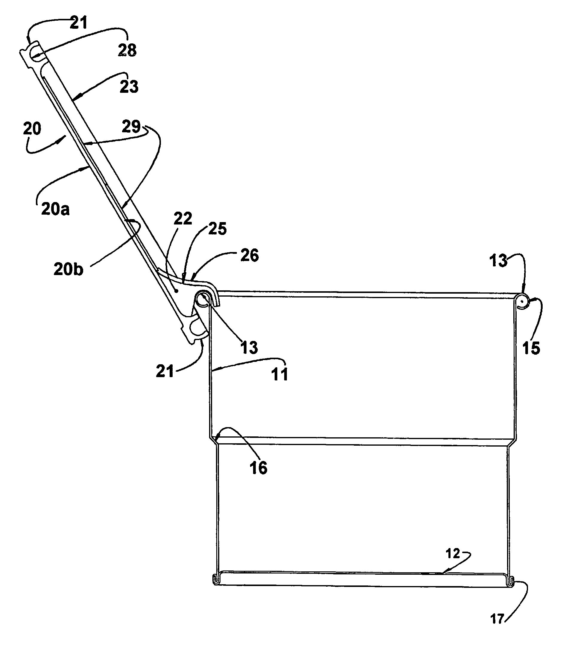
[0011]The construction above allows the lid, which is provided with only one simple lower support means, to be rapidly and easily removed from the body of the container and readapted thereto in an inverted position, utilizing an upper edge portion of the body and one of its lateral walls as elements for supporting and positioning the lid in the inverted inclined position in order to operate as a paint drip tray.

Problems solved by technology

In U.S. Pat. No. 3,828,389, the lid is formed in a single piece with the body of the container, requiring the utilization of plastic material for the formation of the one-piece body-lid combination, which leads to a relatively high cost construction.
This construction is complex and expensive, requiring the formation of a tilting cover in the container lid itself.
Besides complex and expensive, this construction requires the lower edge of the lid-tray to be positioned in the interior of the container body and at least initially immersed in the paint.
The provision of the internal lateral supports complicates the construction, even considering the formation of the container body in plastic material.
For containers in which the body is made of metallic sheet, this construction is unacceptably complex.

Method used


Image

  • Removable lid of a paint container
  • Removable lid of a paint container
  • Removable lid of a paint container

Examples


Embodiment Construction

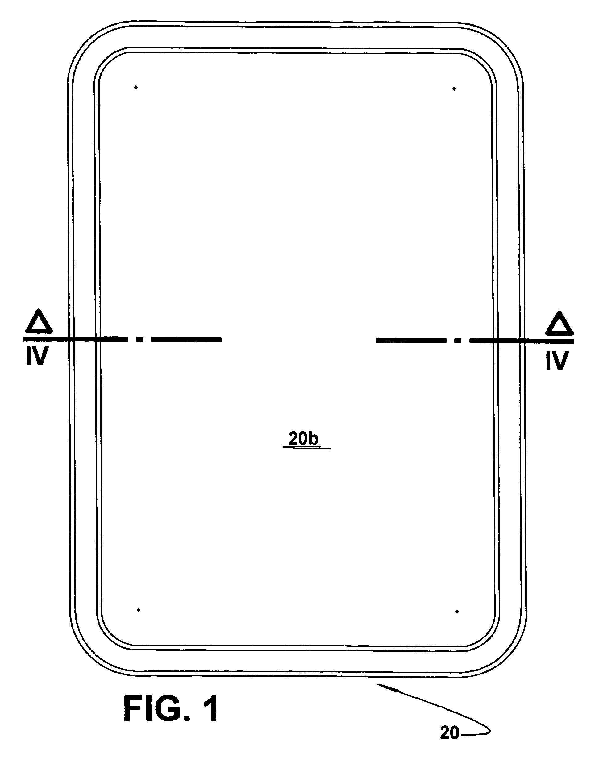
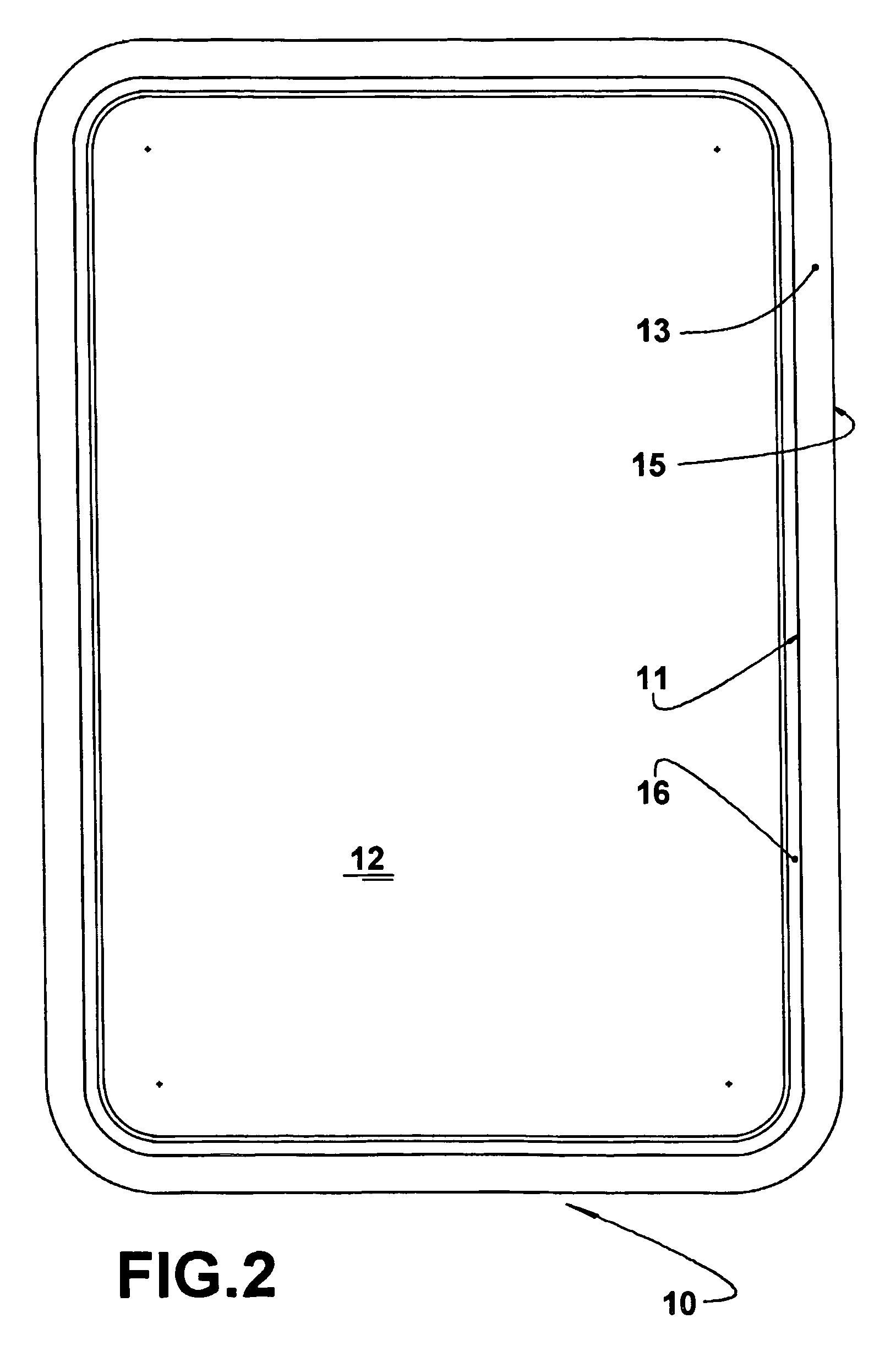
[0018]As illustrated in the figures of the enclosed drawings, the present paint container is of the type which comprises a body 10 with a generally rectangular polygonal cross section and which is defined by a plurality of lateral walls 11, whose lower edges are interconnected by a bottom wall 12 and whose upper edges define respective upper edge portions 13 of the body 10.

[0019]The body 10 is preferably constructed in metallic sheet, defining a can with a substantially parallelepipedic contour and which is superiorly opened and dimensioned to store a determined volume of paint.

[0020]It should be understood that the body 10 might be constructed in other adequate materials, such as injected plastic. Independently of the material with which the body 10 is made, the latter must present a cross section dimensioned to allow the introduction of a paint instrument, which may be defined by a paint roller or by any brush. In the case of paint containers of the type used for painting construc...


PUM


Abstract

A paint container, comprising a body (10) with a polygonal cross section, presenting upper edge portions (13) and a lid (20) having lateral edge portions (21) which are removably seated and tightly retained in a seat (15) defined along the upper edge portions (13) of the body (10). The lid (20) presents a lower face (20a) incorporating a downwardly projecting support means (22) which is engaged with an adjacent upper edge portion (13) of the body (10) after the opening of the lid (20), in order to maintain the latter with its adjacent lateral edge portion (21) externally seated against the lateral wall (11) of the body (10) and in an inclined position with its lower face (20a) forming a paint drip tray, said support means (22) defining a deflecting chute (25) for directing, to the interior of the body (10), the paint that is gravitationally dripping down the internal face (20a) of the lid (20).

Description

CROSS REFERENCE TO PRIOR APPLICATION[0001]This is a U.S. national phase application under 35 U.S.C. §371 of International Patent Application No. PCT / BR2004 / 000157, filed Aug. 25, 2004, and claims benefit of Brazilian Patent Application No. PI 0303764-9, filed Aug. 29, 2003 which is incorporated by reference herein. The International Application was published in English on Mar. 10, 2005 as WO 2005 / 021287 A3 under PCT Article 21(2).FIELD OF THE INVENTION[0002]The present invention refers to a container, such as a can, for storing a volume of paint and which is defined by a body superiorly closed by a removable reclosable lid, which is constructed to operate also as a paint drip tray to be used with rollers or other painting instruments which are wetted with paint when directly immersed in the content of the container.PRIOR ART[0003]The state of the art related to the object of the present invention provides different paint container constructions, according to which the container body...

Claims


Application Information

Patent Timeline
Patent Type & Authority Patents(United States)
IPC IPC(8): B65D43/03B44D3/12B65D43/02
CPCB44D3/127B44D3/128
Inventor ALVARES, ANTONIO CARLOS TEIXEIRA
Owner BRASILATA S A EMBALAGENS METALICAS
Learn More