Systems and Methods for Electro-hydrodynamic Wind Energy Conversion

a technology of wind energy conversion and electrohydrodynamics, applied in the direction of kinetic-electric generators, generators/motors, lighting and heating apparatuses, etc., can solve the problems of high cost, unsuitability for certain areas, and inability to meet the needs of use, and achieve the effect of improving the efficiency of the existing ehd wind energy conversion devi

Active Publication Date: 2013-01-17
GENERAL ELECTRIC CO
View PDF0 Cites 26 Cited by
  • Summary
  • Abstract
  • Description
  • Claims
  • Application Information

AI Technical Summary

Problems solved by technology

Although these wind turbines have proved to be highly successful in onshore and offshore windy regions, they require expensive parts and are often viewed as unaesthetic objects.
Moreover, as the mechanical wind turbines include noisy rotating and moving parts, they are unsuitable for certain areas.
These devices do not generate electricity through the motion of any moving parts; instead, they generate electricity by generating small electrically charged liquid droplets and / or solid particles and introducing them into the wind path.
Existing EHD wind energy conversion devices, however, may not be very efficient.
However, as the nozzles are point sources, they may not be able to produce a large number of droplets or droplets having small dimensions optimal for EHD power conversion.
For example, if the drops are too large, the drag force of low speed winds may be insufficient to carry the droplets effectively, and if the number of droplets is too low, it may lead to lower power generation.

Method used


Image

  • Systems and Methods for Electro-hydrodynamic Wind Energy Conversion
  • Systems and Methods for Electro-hydrodynamic Wind Energy Conversion
  • Systems and Methods for Electro-hydrodynamic Wind Energy Conversion

Examples


Embodiment Construction

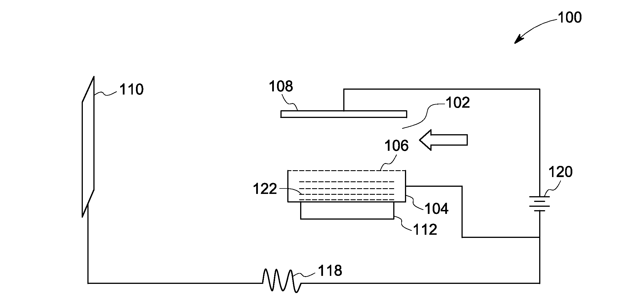
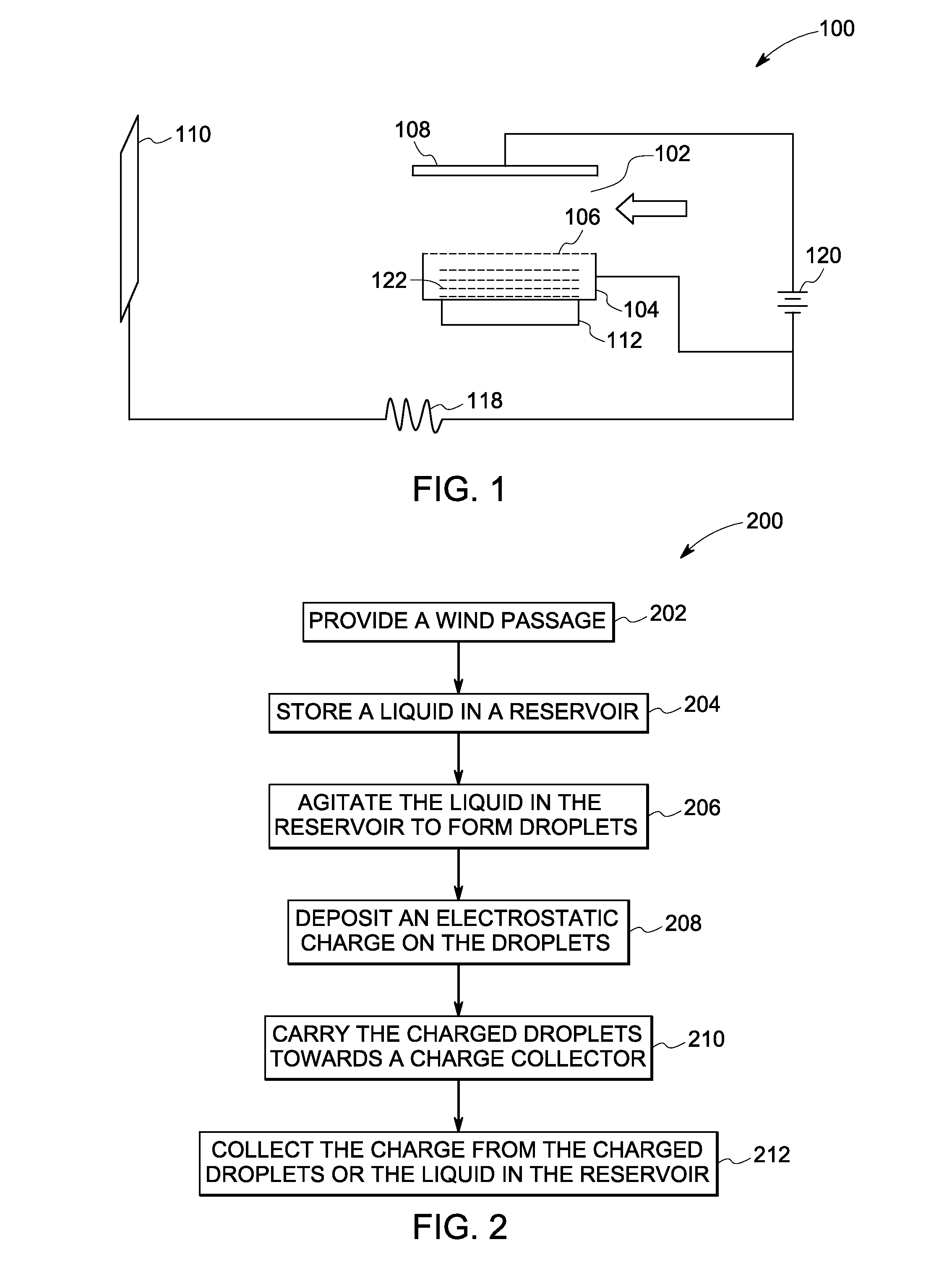
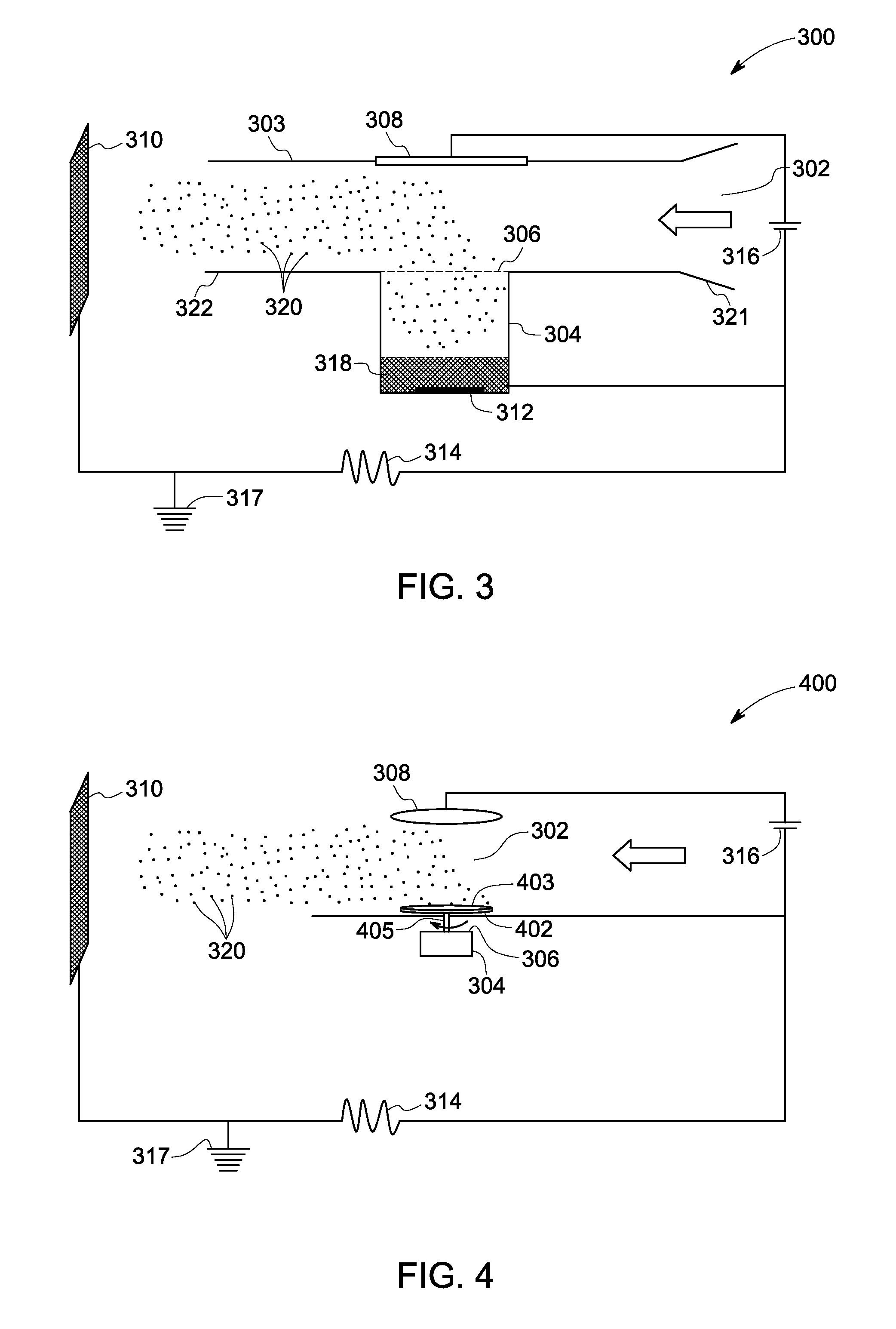
[0015]Embodiments of the present disclosure are related to a system and method for electro-hydrodynamically extracting electrical energy from wind. The systems described hereinafter generate a large number of micron-sized droplets, which increase the cumulative charge generated by the system, and in turn enhance the efficiency of the system.

[0016]Conventional solutions that utilize electrosprays or nozzles to generate charged droplets fail to produce a large number of droplets. In particular, in a conventional electrospray system pressurized liquid is dispensed through a pointed end of a nozzle to produce droplets, thereby resulting in the generation of a limited number of droplets. To increase the number of droplets generated, these systems can increase the size of the orifices. However, increasing the size of the orifices results in an increase in the droplet size. It may be noted that in certain cases no droplets may be formed because of the large orifice size. Alternatively, the...


PUM


Abstract

An electro-hydrodynamic wind energy conversion system is presented. The system includes a wind passage allowing wind flow. Further, the system includes a reservoir having an opening in communication with the wind passage and configured to hold a liquid. The system also includes an agitator coupled to the reservoir and configured to convert the liquid into droplets. Additionally, the system includes a charging system disposed substantially opposite the reservoir opening and configured to deposit an electrostatic charge on the droplets and draw the droplets into the wind passage. Moreover, the system includes a charge collector disposed at a distal end of the wind passage and configured to collect the electrostatic charge from the droplets.

Description

BACKGROUND[0001]Embodiments of the present disclosure relate to wind energy conversion devices, and more particularly to electro-hydrodynamic wind energy conversion devices.[0002]Traditional wind energy conversion devices like wind turbines include multiple mechanical rotating or moving parts such as rotor blades, shafts, generators, gearboxes, brakes, and the like. Wind impinging on the blades causes the blades to rotate. This rotation is converted into electrical energy by a generator that is coupled to the blades. Although these wind turbines have proved to be highly successful in onshore and offshore windy regions, they require expensive parts and are often viewed as unaesthetic objects. Moreover, as the mechanical wind turbines include noisy rotating and moving parts, they are unsuitable for certain areas.[0003]Recently, as an alternative to the mechanical wind turbines, wind energy conversion devices that work on the principles of electro-hydrodynamics (EHD) have been develope...

Claims


Application Information

Patent Timeline
Patent Type & Authority Applications(United States)
IPC IPC(8): B05B5/053
CPCH02N3/00B05B5/0255B05B17/0615B05B7/0075B05B3/1014B05B7/0012
Inventor KALRA, CHIRANJEEVSEELEY, CHARLES ERKLINOPAITS, DMYTRO FLORIYOVYCHSONI, SUNILKUMAR ONKARNATHLEONARD, GARY LEE
Owner GENERAL ELECTRIC CO
Why Eureka
Try Eureka