Capacitance-type detecting device

a detection device and capacitance type technology, applied in the direction of measuring devices, resistance/reactance/impedence, instruments, etc., can solve the problems of detection error, difficult to accurately detect the finger of the operator which touches and difficult to accurately detect the object to be detected which approaches the edge of the sensor substrate and the object to be detected which approaches the center of the sensor substrate. , to achieve the effect of reducing the difference in detection sensitivity and high accuracy

Active Publication Date: 2013-01-17
ALPS ALPINE CO LTD
View PDF4 Cites 37 Cited by
  • Summary
  • Abstract
  • Description
  • Claims
  • Application Information

AI Technical Summary

Benefits of technology

[0009]According to this structure, the difference between a capacitance variation when an object to be detected approaches the low sensitivity region and a capacitance variation when the object to be detected approaches the high sensitivity region is reduced. Therefore, the difference between the detection sensitivity of the object to be detected in the low sensitivity region and the detection sensitivity of the object to be detected in the high sensitivity region is reduced and it is possible to reduce the difference in the detection sensitivity in the detection target region. In addition, even when a plurality of objects to be detected approach the low sensitivity region and the high sensitivity region in the detection target region, it is possible to detect the objects to be detected in the low sensitivity region and the high sensitivity region and thus achieve multi-point detection with high accuracy.

Problems solved by technology

Therefore, in the capacitance-type touch panel according to the related art, when the touch panel is designed using the capacitance variation at the center of the sensor substrate as a reference, it is difficult to accurately detect the finger of the operator which touches the edge of the sensor substrate.
On the other hand, when a predetermined threshold value is set using the capacitance variation at the edge of the sensor substrate as a reference, a detection error (the object to be detected is detected in a state in which the object to be detected does not touch the sensor surface) occurs in the center of the sensor substrate.
In particular, when multi-point detection is performed to detect all of a plurality of objects to be detected, it is difficult to accurately detect both an object to be detected which approaches the edge of the sensor substrate and an object to be detected which approaches the center of the sensor substrate.

Method used


Image

  • Capacitance-type detecting device
  • Capacitance-type detecting device
  • Capacitance-type detecting device

Examples


Embodiment Construction

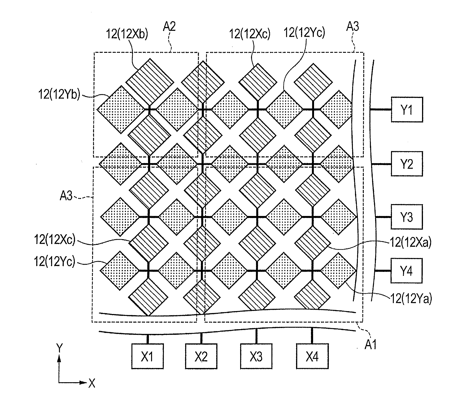
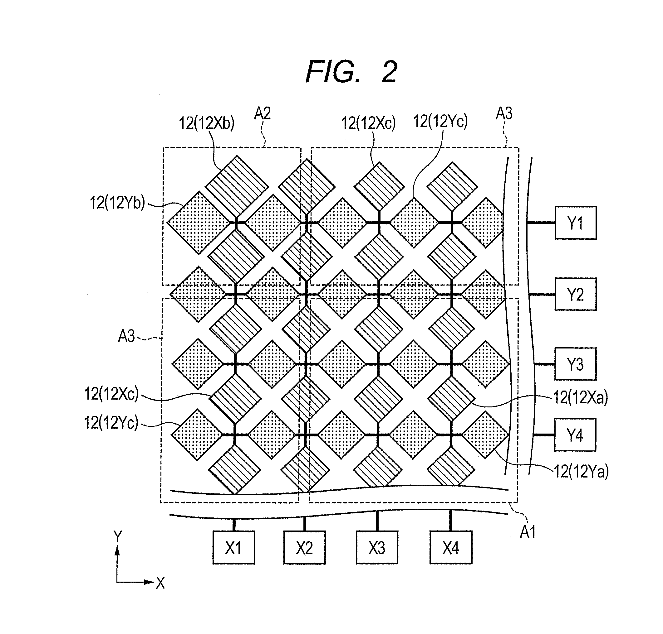
[0017]It is noted that, in a capacitance-type detecting device which detected an object to be detected using a variation in the capacitance formed between a plurality of detecting electrodes, the detection sensitivity of the object to be detected in a detection target region was changed depending on the variation in the capacitance formed between a plurality of detecting electrodes in the detection target region. The inventors found that the magnitude of the capacitance formed in the detection target region was changed depending on the detection sensitivity of the object to be detected in the detection target region to reduce the variation in the capacitance when the object to be detected approached the detection region, thereby achieving the invention.

[0018]Hereinafter, an embodiment of the invention will be described in detail with reference to the accompanying drawings.

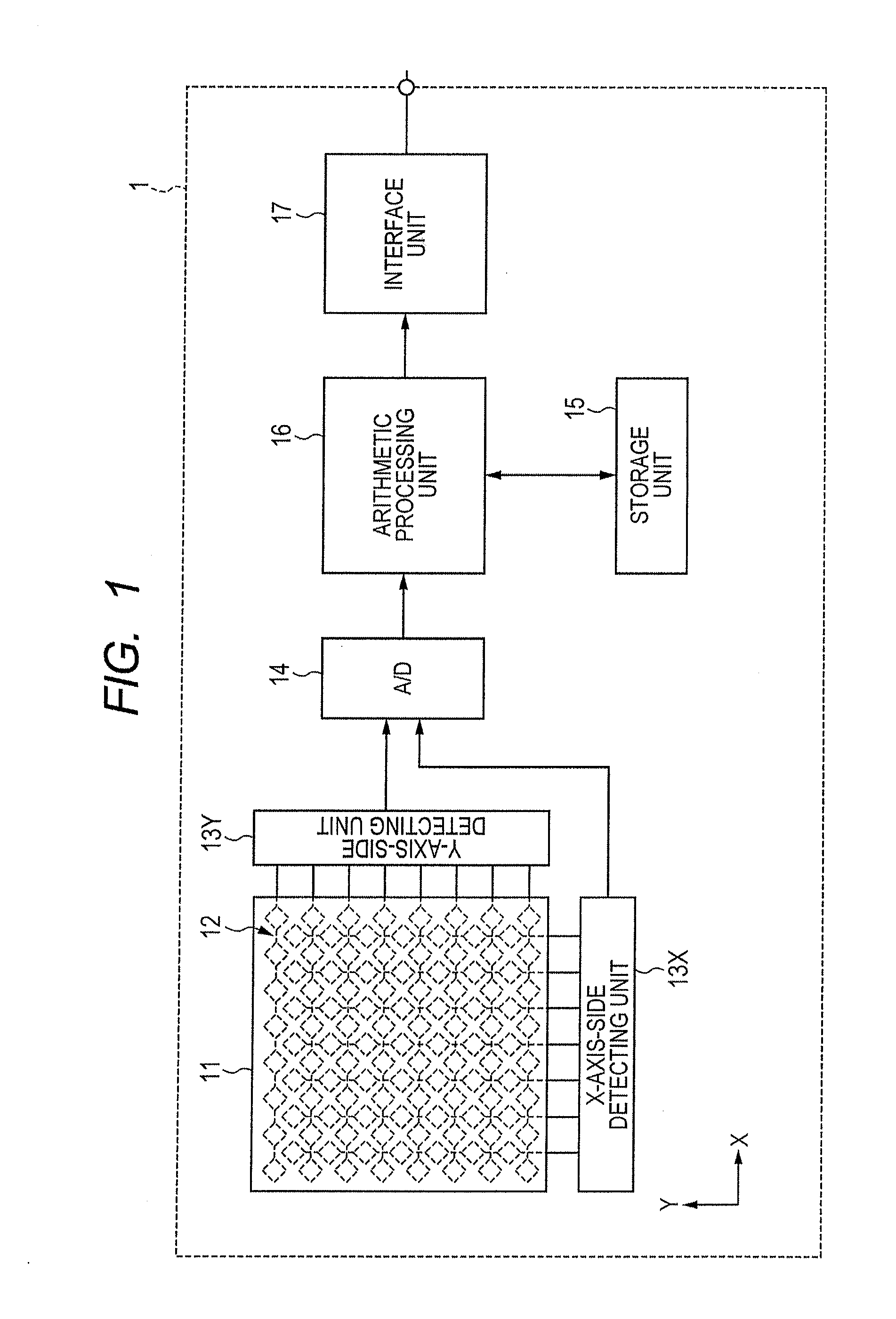
[0019]FIG. 1 is a diagram illustrating the structure of a capacitance-type detecting device according to this em...


PUM


Abstract

A capacitance-type detecting device according to an embodiment of the invention includes a plurality of detecting electrodes that are provided on a sensor substrate such that capacitance is formed between adjacent electrodes. Capacitance formed in a corner detection region in which the detection sensitivity of the sensor substrate is relatively low is more than that formed in a central detection region in which the detection sensitivity is relatively high.

Description

CLAIM OF PRIORITY[0001]This application claims benefit of Japanese Patent Application No. 2011-154955 filed on Jul. 13, 2011, which is hereby incorporated by reference in its entirety.BACKGROUND[0002]1. Field of the Disclosure[0003]The present disclosure relates to a capacitance-type detecting device that detects an object to be detected using a capacitance variation, and more particularly, to a capacitance-type detecting device that detects the coordinates of an object to be detected in a detection target region.[0004]2. Description of the Related Art[0005]Capacitance-type touch panels have been proposed as input devices of various apparatuses (for example, see U.S. Pat. No. 4,550,221). The touch panel includes a plurality of detecting electrodes, which are provided in a houndstooth pattern on a sensor substrate such that a capacitance is formed between adjacent electrodes. The detecting electrodes have a substantially rhombic shape in a plan view and include X-axis electrodes, whi...

Claims


Application Information

Patent Timeline
Patent Type & Authority Applications(United States)
IPC IPC(8): G01R27/26
CPCG06F3/044G06F3/0443G06F3/0446G06F2203/04103G06F2203/04107G06F2203/04111
Inventor IZUMI, HIROSHI
Owner ALPS ALPINE CO LTD
Why Eureka
Try Eureka