Noncontact power feeding apparatus and noncontact power feeding method
- Summary
- Abstract
- Description
- Claims
- Application Information
AI Technical Summary
Benefits of technology
Problems solved by technology
Method used
Image
Examples
first embodiment
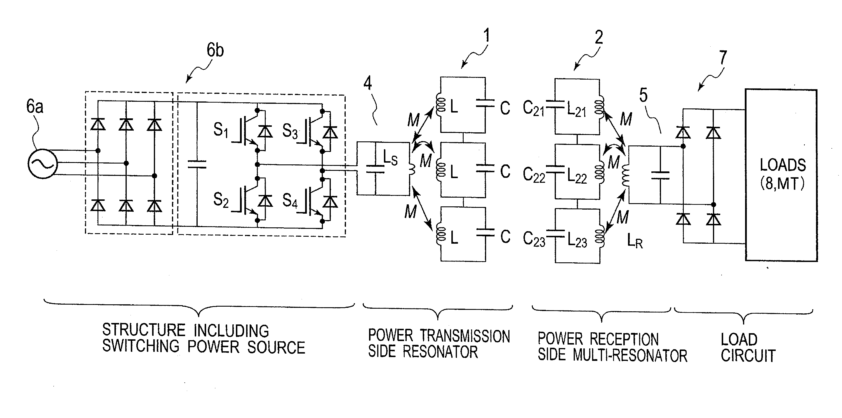
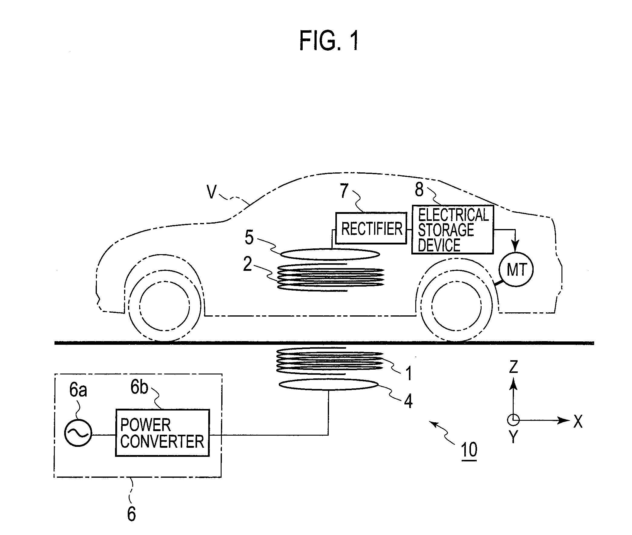
[0025]A first embodiment of the present invention will be described below on the basis of the drawings. In the drawings, the same constituents are denoted by the same reference numerals, and duplicate explanation will be omitted. FIG. 1 is an overall configuration diagram showing a power feeding system for an electric vehicle to which a first embodiment of the present invention is applied, in which the present invention is embodied as a power feeding system for supplying electric power to a driving motor MT of an electric vehicle V.
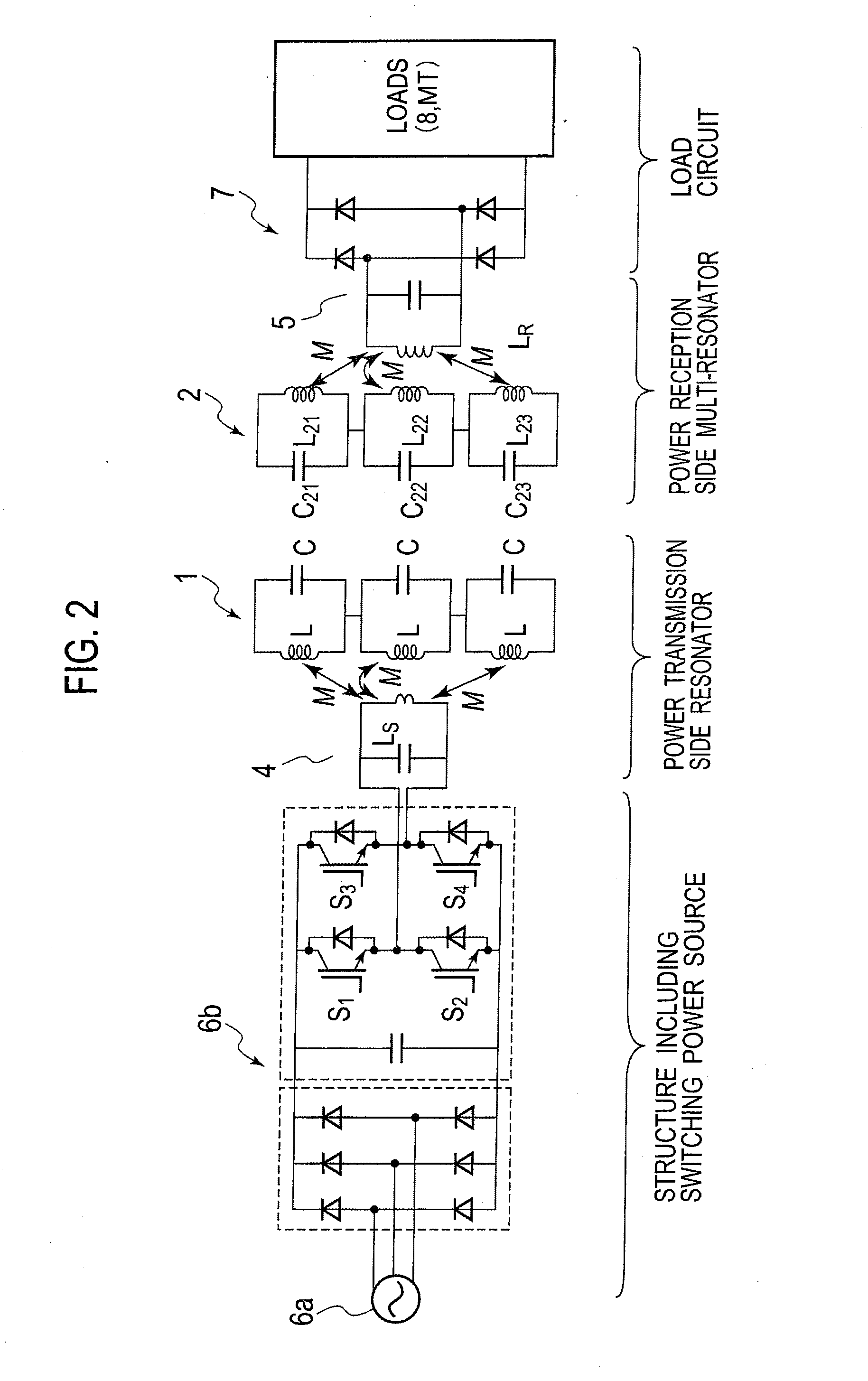
[0026]A power feeding apparatus 10 of the embodiment includes a high-frequency alternating-current power source 6, a primary coil 4, a power transmission coil 1, a power reception coil 2, a secondary coil 5, a rectifier 7, and an electrical storage device 8. Of the power feeding apparatus 10, the power reception coil 2, the secondary coil 5, the rectifier 7, and the electrical storage device 8 are provided in the electric vehicle V, while the high-frequen...
second embodiment
[0052]The number of the LC resonant circuits constituting any of the power transmission coil 1 and the power reception coil 2 is not limited only to the example shown in FIG. 2. For instance, as shown in FIG. 5, a LC resonant circuit constituting the power transmission coil 1 may be formed of one coil L and one capacitor C. In this case, it is preferable to increase a coil diameter so that the coil can be located as close as possible to the multiple LC resonant circuits which constitute the power reception coil 2. Here, the resonant circuits of the power reception coil 2 have to include at least two LC resonant circuits in order to effect the multiple resonant frequencies.
third embodiment
[0053]In the power feeding system shown in FIG. 2, the resonant frequencies f1, f2, f3 of the power reception coil 2 may be set as described below. Like FIG. 4(a), FIG. 6(a) shows the impedance characteristic of the LC resonant circuits constituting the power transmission coil 1. Like FIG. 4(b), FIG. 6(b) shows the impedance characteristics of the LC resonant circuits constituting the power reception coil 2. Specifically, dashed lines in FIG. 6(b) show the respective impedance characteristics of the three LC resonant circuits constituting the power reception coil 2. A solid line in FIG. 6(b) shows an overall impedance characteristic of the three LC resonant circuits obtained by combining the impedance characteristics of the three LC resonant circuits together. At least one of the resonant frequencies f1, f2, f3 of the three LC resonant circuits is set within a range of the half width Δf an adjacent one of the resonant frequencies. Accordingly, the combined impedance characteristic o...
PUM
 Abstract
Description
Claims
Application Information
 - R&D
- Intellectual Property
- Life Sciences
- Materials
- Tech Scout
- Unparalleled Data Quality
- Higher Quality Content
- 60% Fewer Hallucinations
Browse by: Latest US Patents, China's latest patents, Technical Efficacy Thesaurus, Application Domain, Technology Topic, Popular Technical Reports.
© 2025 PatSnap. All rights reserved.Legal|Privacy policy|Modern Slavery Act Transparency Statement|Sitemap|About US| Contact US: help@patsnap.com


