Eureka AIR delivers breakthrough ideas for toughest innovation challenges, trusted by R&D personnel around the world.

Doubly-fed induction generator system and the self-test method for the active crowbar circuit thereof

Active Publication Date: 2013-01-31
DELTA ELECTRONICS SHANGHAI CO LTD
View PDF3 Cites 17 Cited by
  • Summary
  • Abstract
  • Description
  • Claims
  • Application Information

AI Technical Summary

Benefits of technology

This patent describes a system for generating electricity using a special generator called a doubly-fed induction generator. This system also includes a way to check the health of the generator's active crowbar circuit, without causing any harm to the overall operation of the system. The technical effect of this patent is to improve the reliability and efficiency of the doubly-fed induction generator system.

Problems solved by technology

However, the disadvantage of such type of self-test method is that the voltage across the bridge arm is uncertain due to the parasite capacitors when the IGBT switch of the active crowbar circuit is turned off.
MTherefore, the threshold voltage for testing if the IGBT switch is turned on is difficult to design, and a voltage sensor is needed for voltage detection.
However, such type of self-test method also has some disadvantages.
If the rotor-side converter and the IGBT switch of the active crowbar circuit are turned on simultaneously by the PWM signal, it will cause the over-current problem to the rotor-side converter.

Method used


Image

  • Doubly-fed induction generator system and the self-test method for the active crowbar circuit thereof
  • Doubly-fed induction generator system and the self-test method for the active crowbar circuit thereof
  • Doubly-fed induction generator system and the self-test method for the active crowbar circuit thereof

Examples


Embodiment Construction

[0013]An exemplary embodiment embodying the features and advantages of the invention will be expounded in following paragraphs of descriptions. It is to be realized that the present invention is allowed to have various modification in different respects, all of which are without departing from the scope of the present invention, and the description herein and the drawings are to be taken as illustrative in nature, but not to be taken as a confinement for the invention.

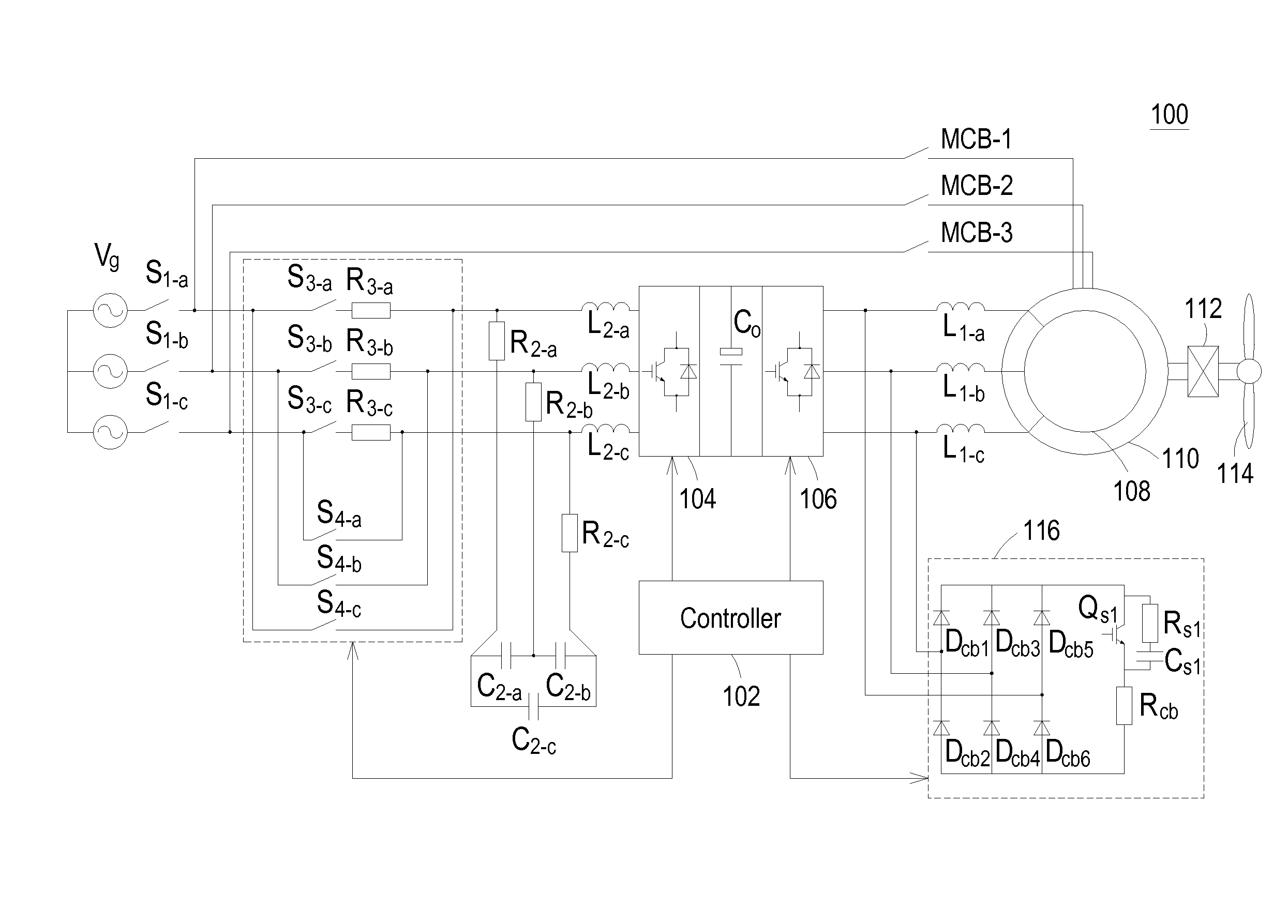
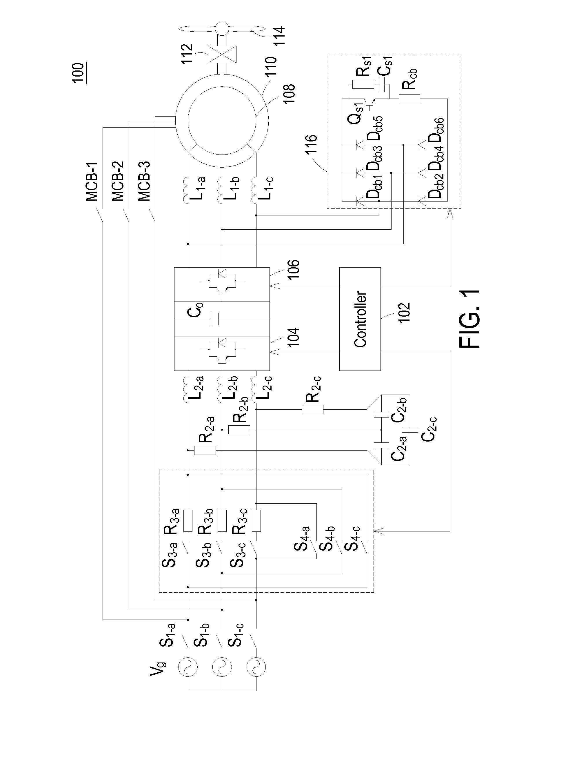
[0014]FIG. 1 is a circuit block diagram showing the doubly-fed induction generator system according to the invention. As shown in FIG. 1, the inventive doubly-fed induction generator system 100 includes a grid Vg for providing a three-phase AC voltage. The inventive doubly-fed induction generator system 100 further includes a soft-start circuit connected to the grid Vg through a three-phase switch (S1-a, S1-b, S1-c). The soft-start circuit includes switches S3-a, S3-b, S3-c, switches S4-a, S4-b, S4-c, and resistors R3-...


PUM


Abstract

Provided is a doubly-fed induction generator system and a self-test method for the active crowbar circuit of the doubly-fed induction generator system. The invention is featured by using the controller of the doubly-fed induction generator system to carry out a self-test procedure to detect the loop current of the active crowbar circuit for determining if the active crowbar circuit can be turned on and off normally. Also, the rotor-side converter and the active crowbar circuit of the doubly-fed induction generator system are forbidden to turn on simultaneously during the execution of the self-test procedure.

Description

FIELD OF THE INVENTION[0001]The invention relates to a doubly-fed induction generator system, and more particularly to a doubly-fed induction generator system having an active crowbar circuit for implementing the function of low-voltage ride-through (LVRT).BACKGROUND OF THE INVENTION[0002]The contemporary wind turbine principally employs a doubly-fed induction generator (DFIG) as the major wind generator. When the power grid is abnormal and the voltage of point of common connection (PCC) is sagged, the doubly-fed induction generator has to keep connected to the grid until the grid returns to the normal state, thereby riding through this low-voltage period (zone). Therefore, the doubly-fed induction generator generally is required to have the function of low-voltage ride-through (LVRT). Nowadays, the most common LVRT technique applied to the doubly-fed induction generator is active crowbar circuit. The active crowbar circuit is used to protect the rotor-side circuitry of the doubly-f...

Claims


Application Information

Patent Timeline
IPC IPC(8): H02P9/02
CPCG01R31/2827G01R31/343H02H7/06H02H7/12H02H9/002
Inventor ZHENG, JIANFEILU, FEILI, ZHIQIU, AIBIN
Owner DELTA ELECTRONICS SHANGHAI CO LTD
Why Eureka
Eureka Blog
Learn More