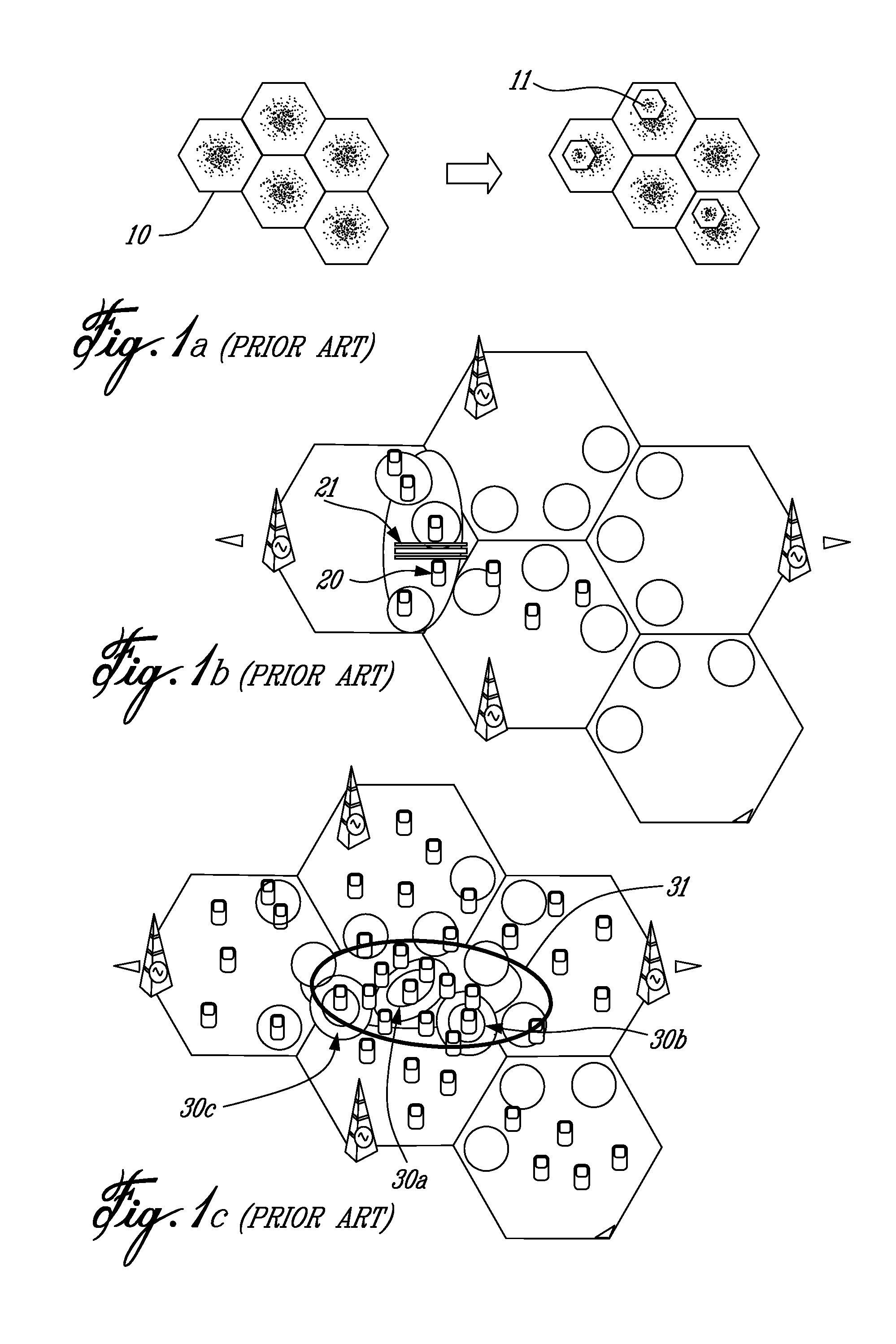
A challenging question for operators is how to evolve their existing cellular networks so as to meet the requirement for higher data rates.
Building a denser macro
base station grid, while simultaneously enhancing the cooperation between macro base stations (hence either using options i) or ii) above) is definitely a solution that meets the requirement for higher data rates; however such an approach is not necessarily a cost-efficient option, due to the costs and delays associated with the installation of macro base stations especially in urban areas where these costs are significant.
However, such a dense deployment of macro base stations would lead to a significantly higher amount of signaling due to frequent handovers for users moving at high speeds.
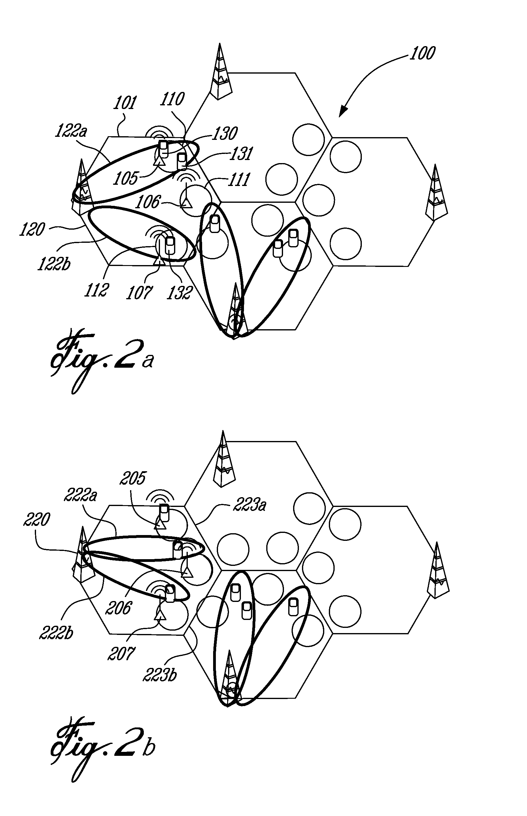
The problem with heterogeneous networks is that small base stations, even if they are easier to deploy and operate than macro base stations, still cannot be deployed everywhere since there are restrictions on where to place them.
Furthermore, often the placement of small base stations or
relay nodes, results in insufficient coverage for all of the users targeted to be served.
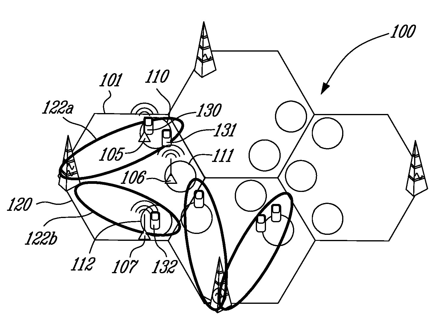
Hence, even after the addition of small base stations around them, there still exists the possibility of users being in coverage holes of the macro layer, and as such they do not necessarily benefit from this addition of small base stations, relays, or low power nodes, in general.
This can happen due to an obstacle, such as a wall, or similar barrier being between the low power node and the user in the macro layer coverage hole.
Moreover, a situation like the one described above might occur even in the case of significant obstacles between the low power nodes and certain users.
Due to the much
higher power transmitted by the macro base stations, low power nodes do not always succeed in absorbing many users.
For example, there might be cases such as the macro layer not providing good coverage to a certain area, and thus users in this area could still connect to the macro base
station rather than to the low power node nearby.
There are also other occasions where the addition of low power nodes does not yield the desired result.
There could be a number of reasons that would cause an operator to not deploy a sufficient amount of macro base stations in such a coverage area.
Reasons include the possibilities that base
station sites are very costly to obtain in this area or the morphology of the area is such that it does not facilitate the provision of high data rates to users therein.
Another reason might be that adding macro base stations is not profitable in this area, considering that this area might be underutilized for a significant percentage of the day, or during the week.
The combination of these two effects mentioned above possibly results in the average
data rate per user in the downlink not being substantially higher than that of the macro cell or probably, the average
data rate per user is not high relative to the desired level.

