
Three dimensional display panel and phase retardation film thereof

a three-dimensional display panel and phase retardation technology, applied in the field of display panels, can solve the problems of reducing the brightness of the 3d display panel, the method of reducing the size of the pixel unit is very expensive, and the quality of the viewing experience is not good enough, so as to eliminate the discontinuousness of the image viewed and improve the discontinuousness of the 3d image viewed

Inactive Publication Date: 2013-02-07
BENQ MATERIALS CORP
View PDF2 Cites 7 Cited by
  • Summary
  • Abstract
  • Description
  • Claims
  • Application Information

AI Technical Summary

Benefits of technology

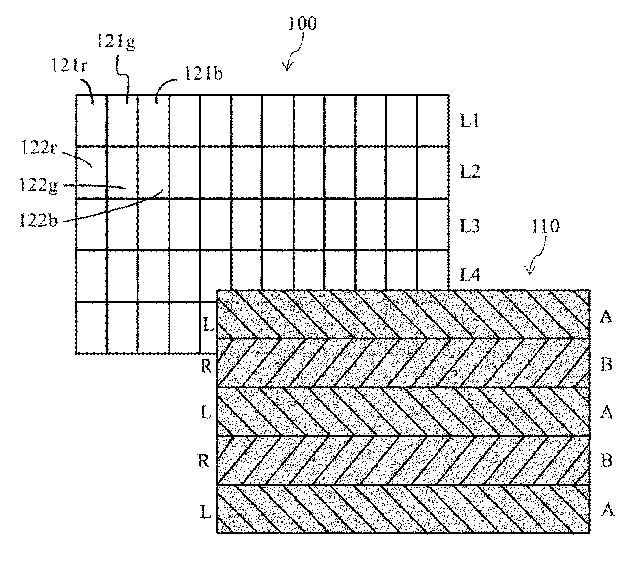
The present invention provides a 3D display panel and a phase retardation film to improve the discontinuousness of the viewed image. The film has alternating phase regions arranged in both horizontal and vertical directions, creating a chessboard-like pattern. This pattern helps to make the image appear more continuous and smooth for the user.

Problems solved by technology

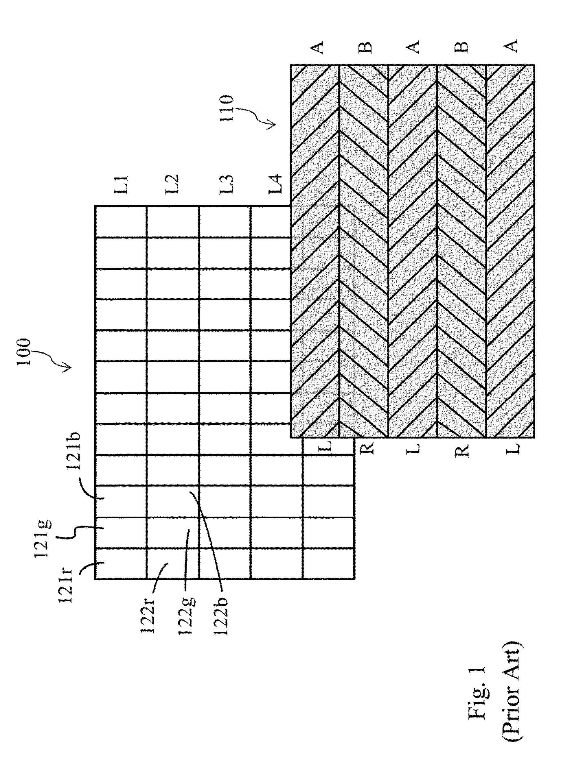
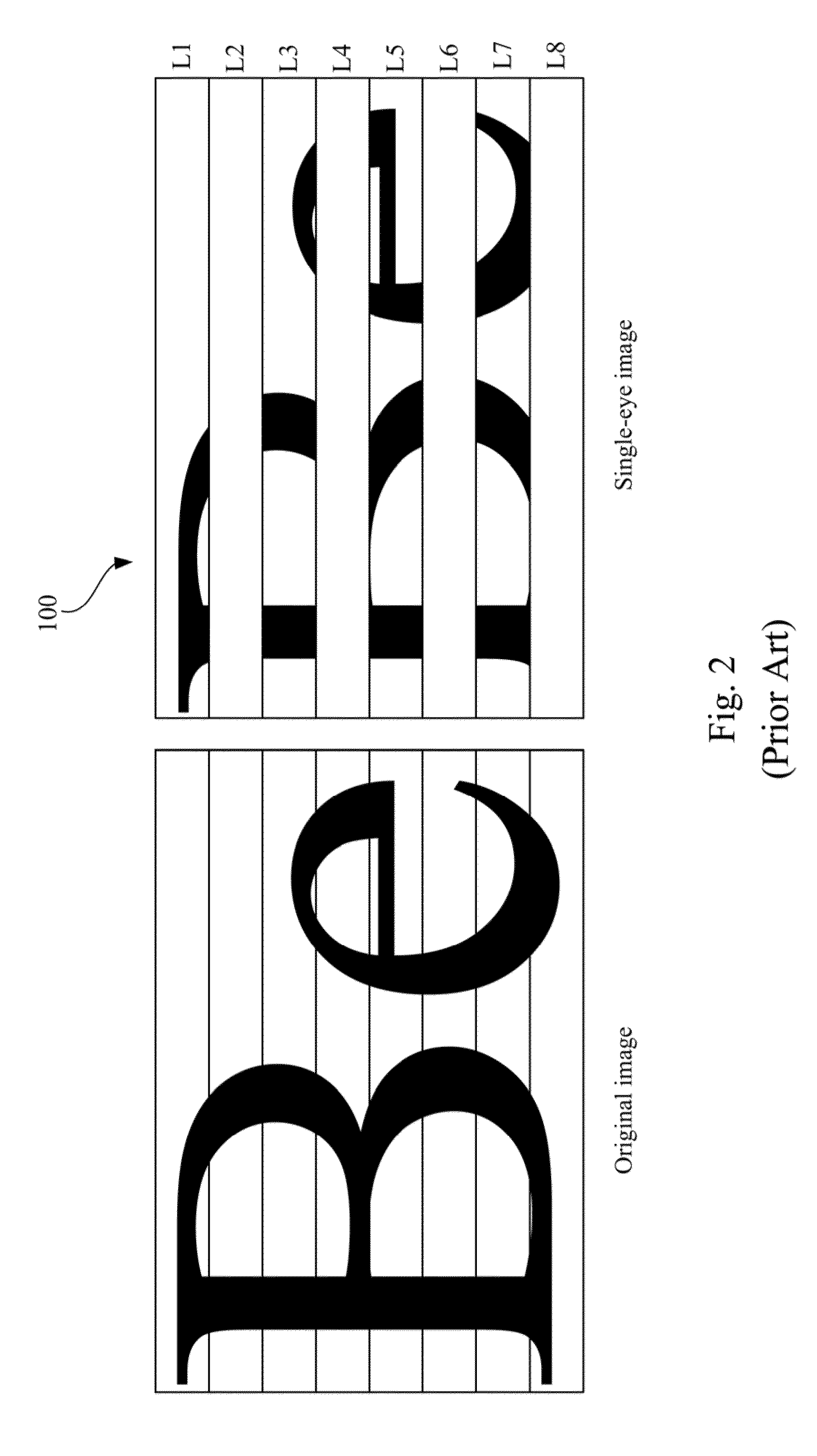
Hence, the image displayed from the conventional 3D display panel 100 is discontinuous and the quality is not good enough for viewing.
However, the method of reducing the size of pixel unit is very expensive and only less light can pass through a smaller pixel unit which would reduce the brightness of 3D display panel.

Method used


Image

  • Three dimensional display panel and phase retardation film thereof
  • Three dimensional display panel and phase retardation film thereof
  • Three dimensional display panel and phase retardation film thereof

Examples


Embodiment Construction

[0021]Please note that the drawings shown in the Figures are for illustrative purposes only and not to scale

[0022]Referring to FIG. 3, FIG. 3 shows pixel units of a 3D display panel 200 of an embodiment of the present invention. The 3D display panel 200 has a plurality of pixel units 221, 222, 223 and 224, wherein each pixel unit further includes a plurality of sub-pixel units corresponding to different display color areas. For example, the pixel unit 221 includes sub-pixel units 221r, 221g and 221b, wherein the sub-pixel unit 221r is corresponding to the display color areas of red color, and the sub-pixel unit 221g is corresponding to the display color areas of green color, and the sub-pixel unit 221b is corresponding to the display color areas of blue color.

[0023]It is noted that the type of the 3D display panel is not limited to a certain type of panel in the present invention. For example, the display panel can be a twisted nematic (TN) LCD panel, a multi-domain vertical alignme...


PUM


Abstract

A three dimensional display panel and a phase retardation film thereof are provided. The three dimensional display panel includes pixel units and a phase retardation film. Each pixel unit includes sub-pixel units corresponding to different color display areas. The phase retardation film includes a plurality of first phase regions and a plurality of second phase adjusting regions. The first phase regions and the second phase regions alternately arranged both in horizontal and vertical directions as a chessboard-like pattern for corresponding to the sub-pixel units, wherein a difference between a phase retardation of the first phase regions and a phase retardation of second phase regions is ½ wavelength (λ).

Description

RELATED APPLICATIONS [0001]This application claims the priority benefit of Taiwan application serial no. 100127763, filed on Aug. 4, 2011, the full disclosure of which is incorporated herein by reference.BACKGROUND OF THE INVENTION[0002]1. Field of the Invention[0003]The invention generally relates to a display panel, and more particularly to a three dimensional (3D) display panel and a phase retardation film thereof.[0004]2. Description of the Related Art[0005]In general, a 3D image displayed on a display device such as a TV or a monitor is constructed by two images with different viewing angles in response to the left eye and the right eye respectively base on a so-called binocular parallax which is the difference between images viewed by two eyes. The left-eye image and the right-eye image are respectively transmitted to the left eye and the right eye through a specific phase retardation film of the 3D display panel and a pair of polarized 3D glasses, thereby forming a 3D image ...

Claims


Application Information

Patent Timeline
Patent Type & Authority Applications(United States)
IPC IPC(8): G02B27/22G02B5/30
CPCG02B27/26G02B5/3083G02B30/25
Inventor HUANG, SHIN-YIHONG, CYUN-TAI
Owner BENQ MATERIALS CORP
Learn More