
Projecting lens set and vibration device
A technology of projection lens and vibrating device, applied in projection devices, televisions, optics, etc., can solve the problems of affecting the continuity of the picture, inconvenience, general products have no structure, etc., and achieve the effect of eliminating the discontinuity of the picture.
- Summary
- Abstract
- Description
- Claims
- Application Information
AI Technical Summary
Problems solved by technology
Method used
Image

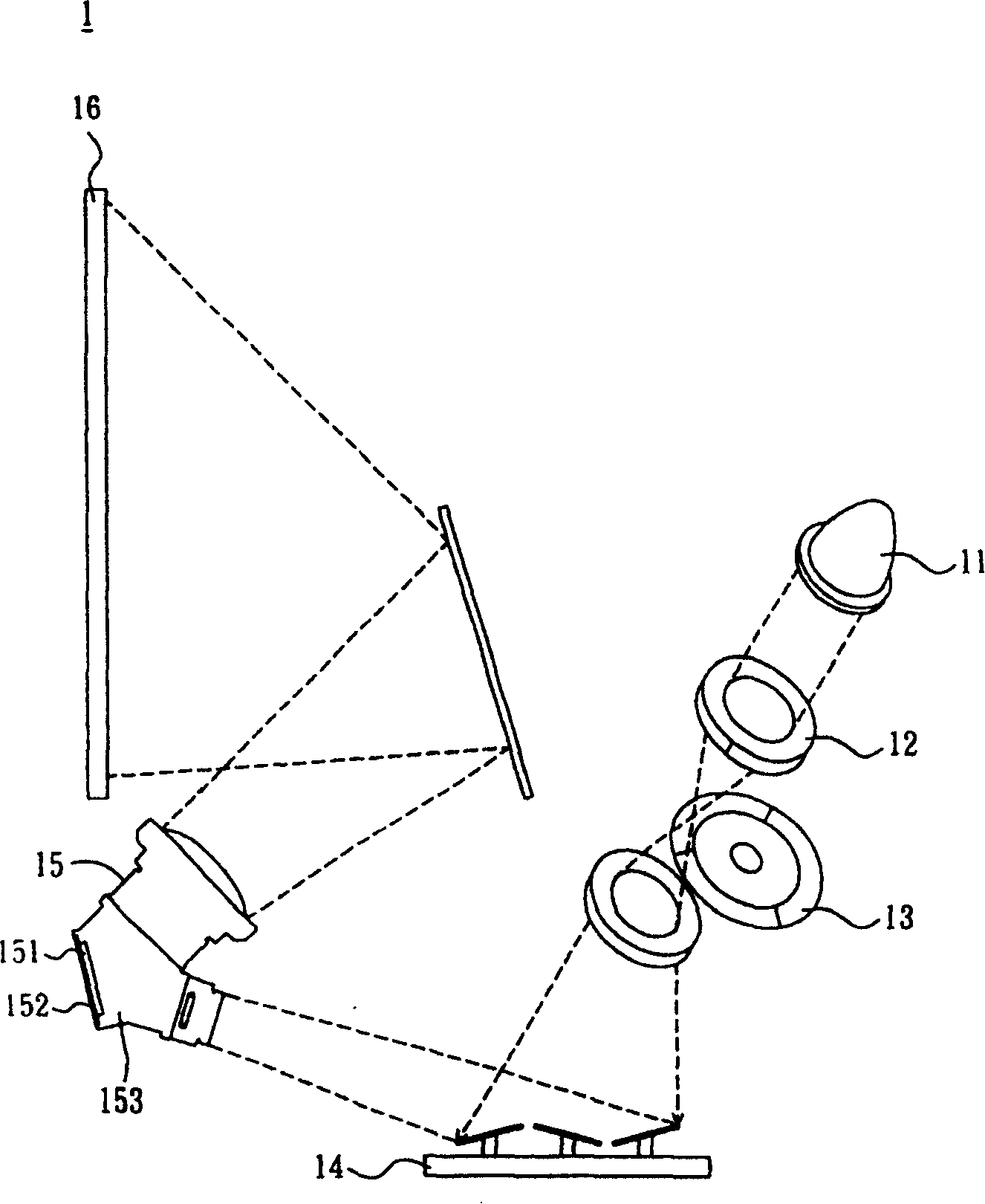
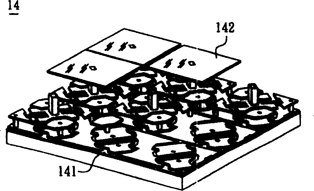
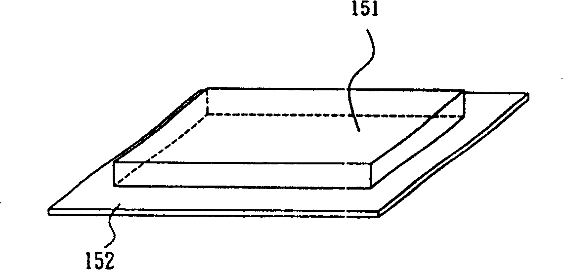
Examples
Embodiment Construction
[0050] In order to further explain the technical means and effects of the present invention to achieve the intended purpose of the invention, the specific implementation, structure and characteristics of the projection lens group and its vibrating device according to the present invention will be described below in conjunction with the accompanying drawings and preferred embodiments. Its functions are described in detail below, and the same elements will be described with the same reference symbols.
[0051] see Figure 4 and Figure 5 Shown is a schematic side view and a top view showing a vibrating device according to a preferred embodiment of the present invention. The vibrating device 2 according to a preferred embodiment of the present invention includes a light reflection element 20, a holding element 21, a base 23, at least one magnetic element 24 and a coil circuit 25, wherein:
[0052] The light reflective element 20 is disposed on the supporting element 21 . In th...
PUM
 Abstract
Description
Claims
Application Information