Dual grip barbell

Inactive Publication Date: 2013-02-07
WIERSZEWSKI NORBERT T
View PDF3 Cites 35 Cited by
  • Summary
  • Abstract
  • Description
  • Claims
  • Application Information

AI Technical Summary

Benefits of technology

[0005]Accordingly, the present invention is directed toward a barbell which overcomes these problems by providing alternate handle combinations for u

Problems solved by technology

A problem with all of these devices is that they are limited to two spaced rotatable handles for the user to grasp at a single spaced separation from one another, despite differences in the exercise being performed or the strength or physique o

Method used


Image

  • Dual grip barbell
  • Dual grip barbell
  • Dual grip barbell

Examples


Example

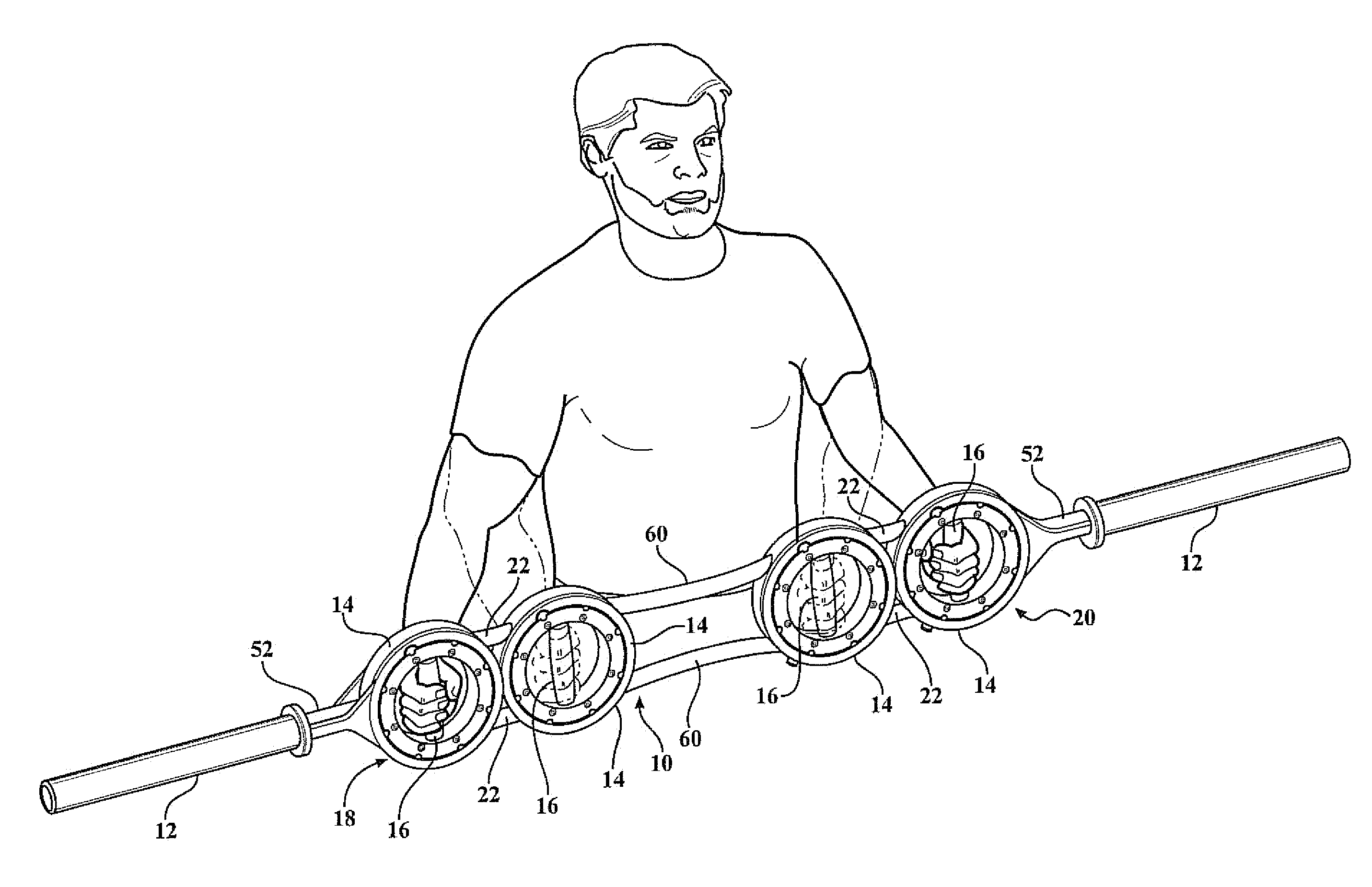
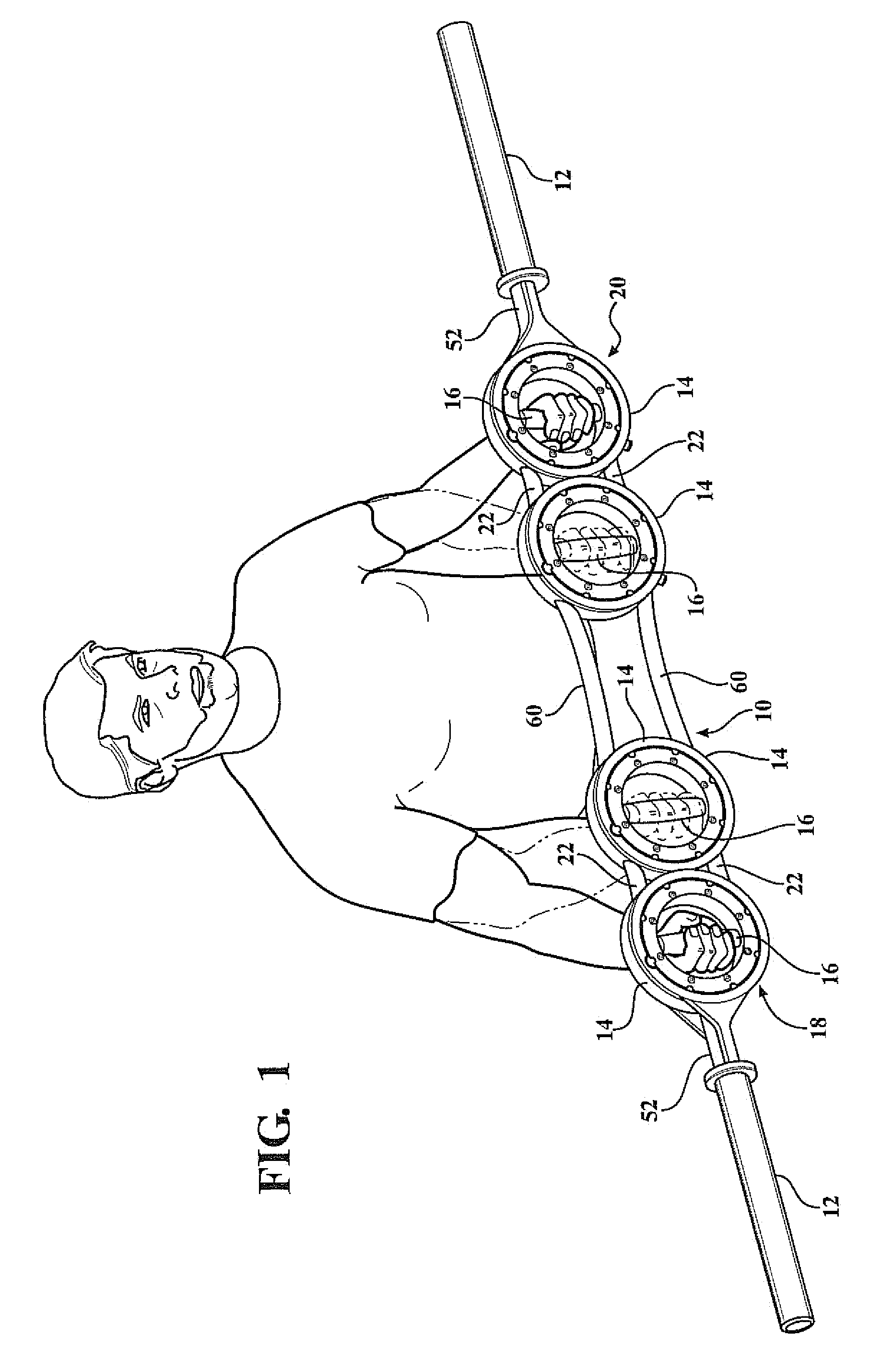
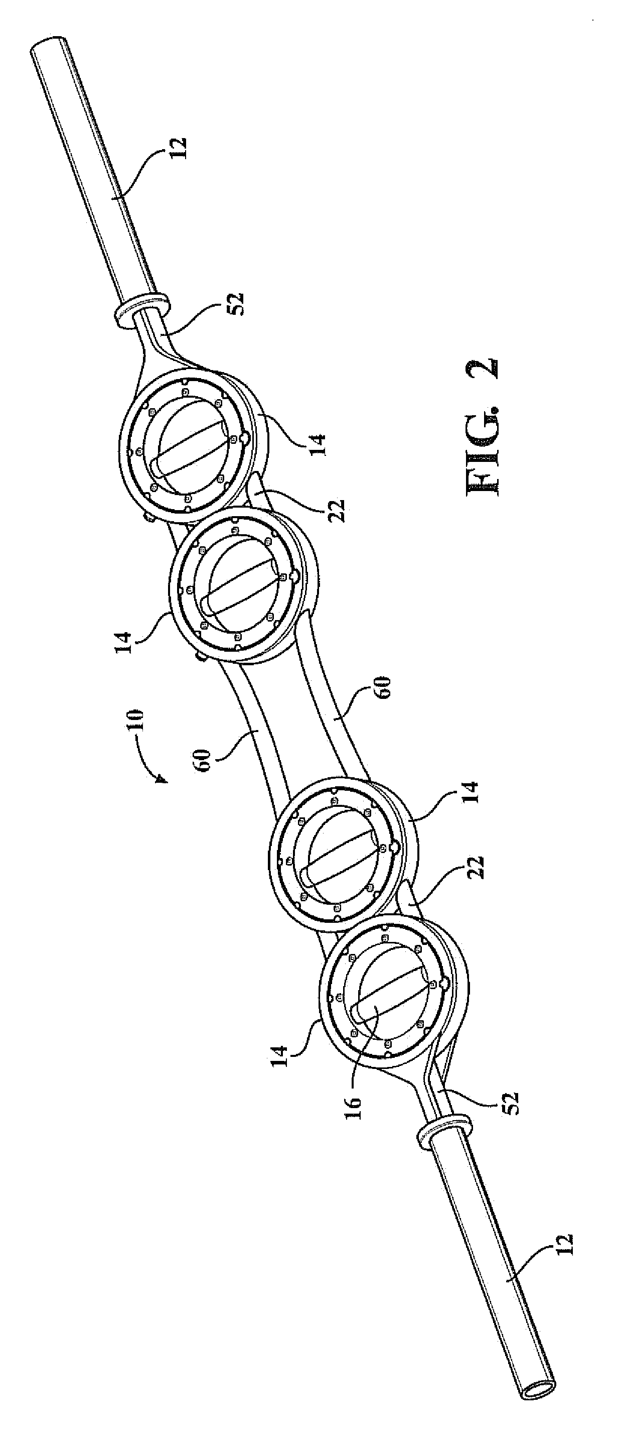
[0015]Referring to the drawings, the barbell of the present invention generally comprises a center section 10 and two end sections 12. The center section 10 comprises four rings 14, each of which supports a rotatable handle 16 which bisects its ring 14 and is rotatably supported within the ring 14. The rings 14 are grouped in two pairs generally indicated at 18 and 20. The two rings in each pair are supported with their adjacent sections abutting one another or relatively closely spaced to one another. The two rings in each pair are joined by short connecting bars 22 with the two bars 22 connecting each pair being disposed symmetrically about the center line of the bar which extends along the projection of the axial end sections 12.

[0016]All of the rings 14 are arrayed in the same plane symmetrically about the center line of the bar.

[0017]FIG. 3 illustrates enlarged detail of one of the two outer rings 14 of each group 18 and 20 and its associated handle 16. Each handle 16 is suppor...


PUM


Abstract

An exercise barbell comprises two separated pairs of rings, all lying along the length of the barbell in a common plane, each ring rotatably supporting a handle member which bisects the ring. The members of each pair are closely separated at their edges, or abutting one another, and are connected by very short bars extending on opposite sides of the center line of the bar. The two pairs are separated by a pair of longer bars disposed on opposite sides of the center line of the bar. Shafts extend outwardly along the length of the barbell from the outermost ring of each pair and these extending shafts may be rotatable, for gripping by the exerciser, and can support individual weights with center holes for surrounding the bar. The dual sets of handles allow a variety of different exercises to be performed with the barbell, most commonly by a user gripping the handle supported in either the two innermost rings or the two outermost rings of each pair.

Description

FIELD OF THE INVENTION[0001]This invention relates to a barbell for exercise purposes such as weightlifting and more particularly to such a barbell comprising two spaced sets of handgrips supported in rings, all lying in a common plane, with each handle bisecting its supporting ring and being rotatably supported within the ring.BACKGROUND OF THE INVENTION[0002]Barbells are commonly used to perform exercises including weightlifting, and it has been proposed to provide rotating handgrips for use in such apparatus so that the user's grip may be accommodated in any rotational position and not restricted to a single angle relative to the axis of the device. U.S. Pat. No. 7,094,186, of which I am an inventor, discloses a barbell with two spaced rings lying in the same plane, with each ring rotatably supporting a bisecting handle that can be adjusted to any angle relative to the bar and may be rotated as the user exercises. Similarly, U.S. Pat. Nos. 3,384,370; 4,618,183; 4,629,184; 5,334,1...

Claims


Application Information

Patent Timeline
IPC IPC(8): A63B21/072
CPCA63B21/1469A63B21/072A63B21/4035
Inventor WIERSZEWSKI, NORBERT T.
Owner WIERSZEWSKI NORBERT T
Why Eureka
Try Eureka