

Cam and link flush slider
- Summary
- Abstract
- Description
- Claims
- Application Information
AI Technical Summary
Benefits of technology
Problems solved by technology
Method used
Image

Examples
Embodiment Construction
[0022] It will be apparent to those skilled in the art, that is, to those who have knowledge or experience in this area of technology, that many uses and design variations are possible for the improved sliding window assembly disclosed herein. The following detailed discussion of various alternative and preferred embodiments will illustrate the general principles of the invention with reference to a sliding window assembly for use as a rear window for a pickup truck or the like. Other embodiments suitable for other applications, such as, for example vans, sport utility vehicles, cross over vehicles, or other motor vehicles will be apparent to those skilled in the art given the benefit of this disclosure.
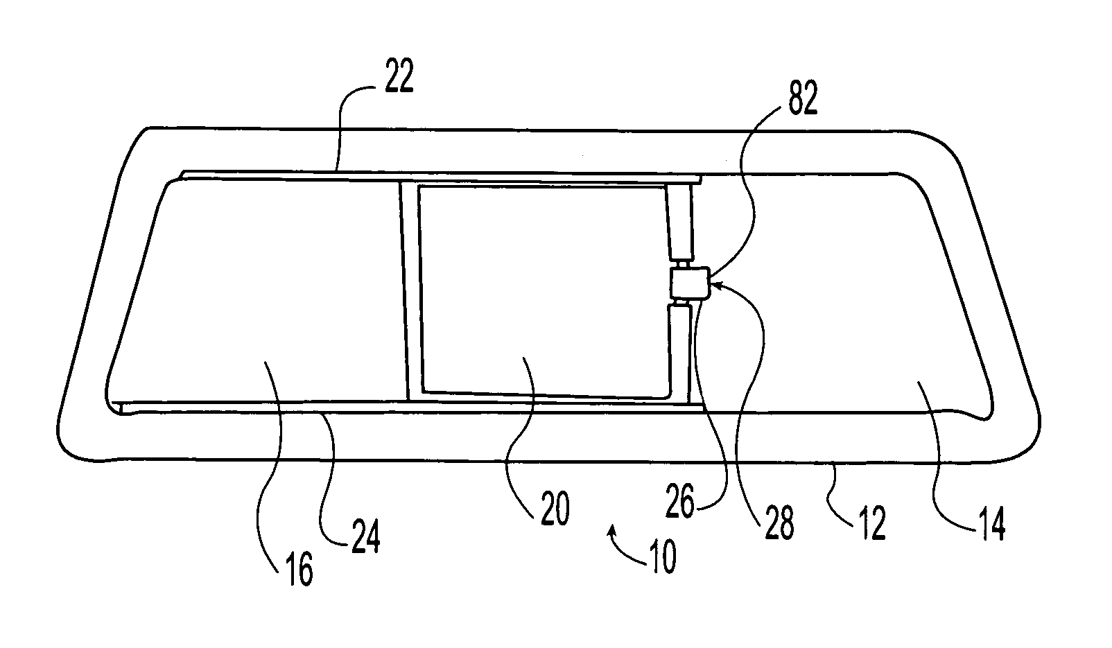
[0023] Referring now to the drawings, FIG. 1 schematically shows a window assembly 10 according to a preferred embodiment of the present invention viewed from a forward or inboard side. The illustrated window assembly 10 includes a circumferential frame 12, a pair of laterally space...
PUM
 Abstract
Description
Claims
Application Information