

Foldable cover
a technology of folding cover and cover plate, which is applied in the direction of rigid containers, instruments, transportation and packaging, etc., can solve the problems of affecting the use of users, affecting the use of the device,
- Summary
- Abstract
- Description
- Claims
- Application Information
AI Technical Summary
Benefits of technology
Problems solved by technology
Method used
Image

Examples
first embodiment
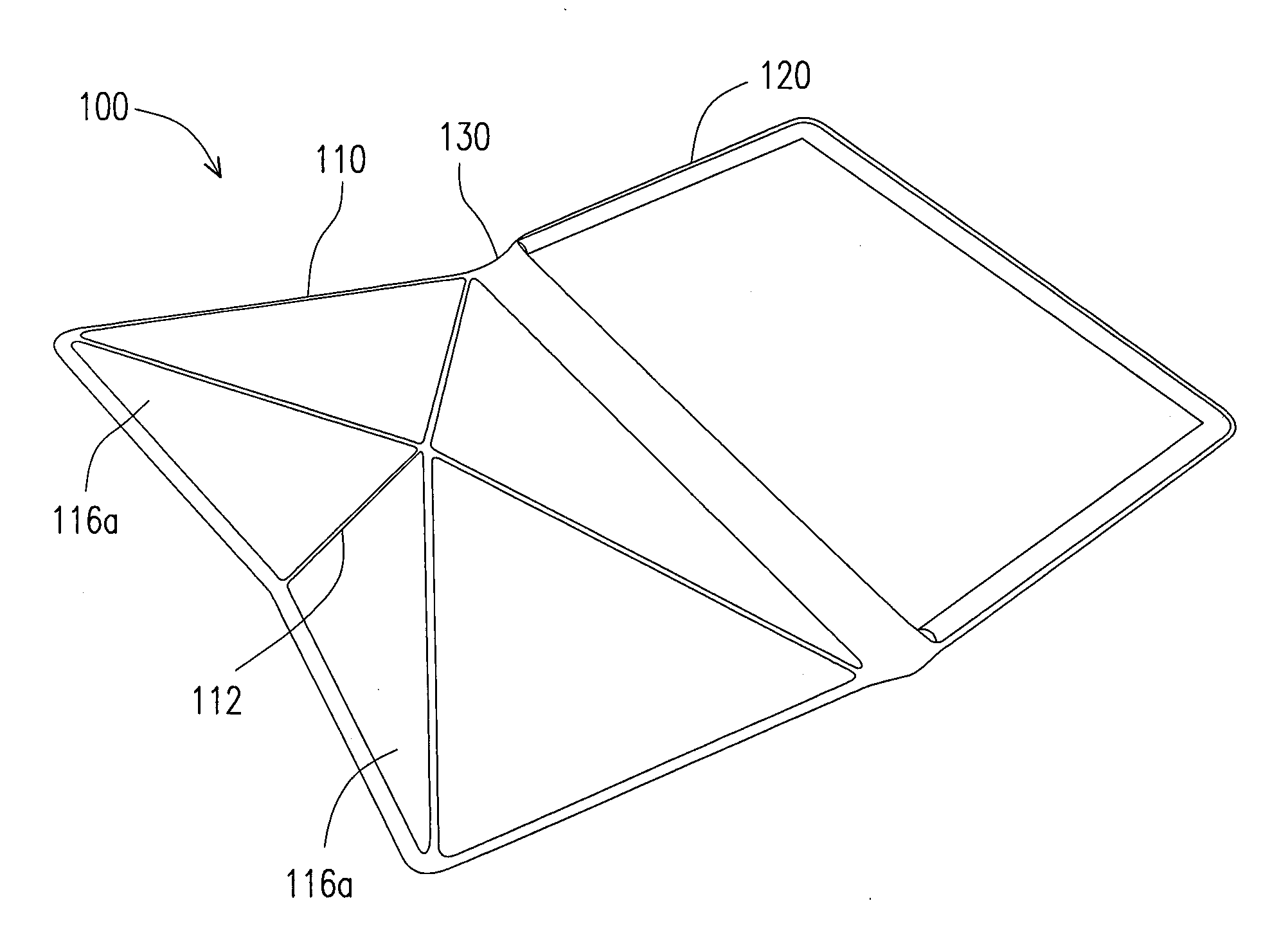
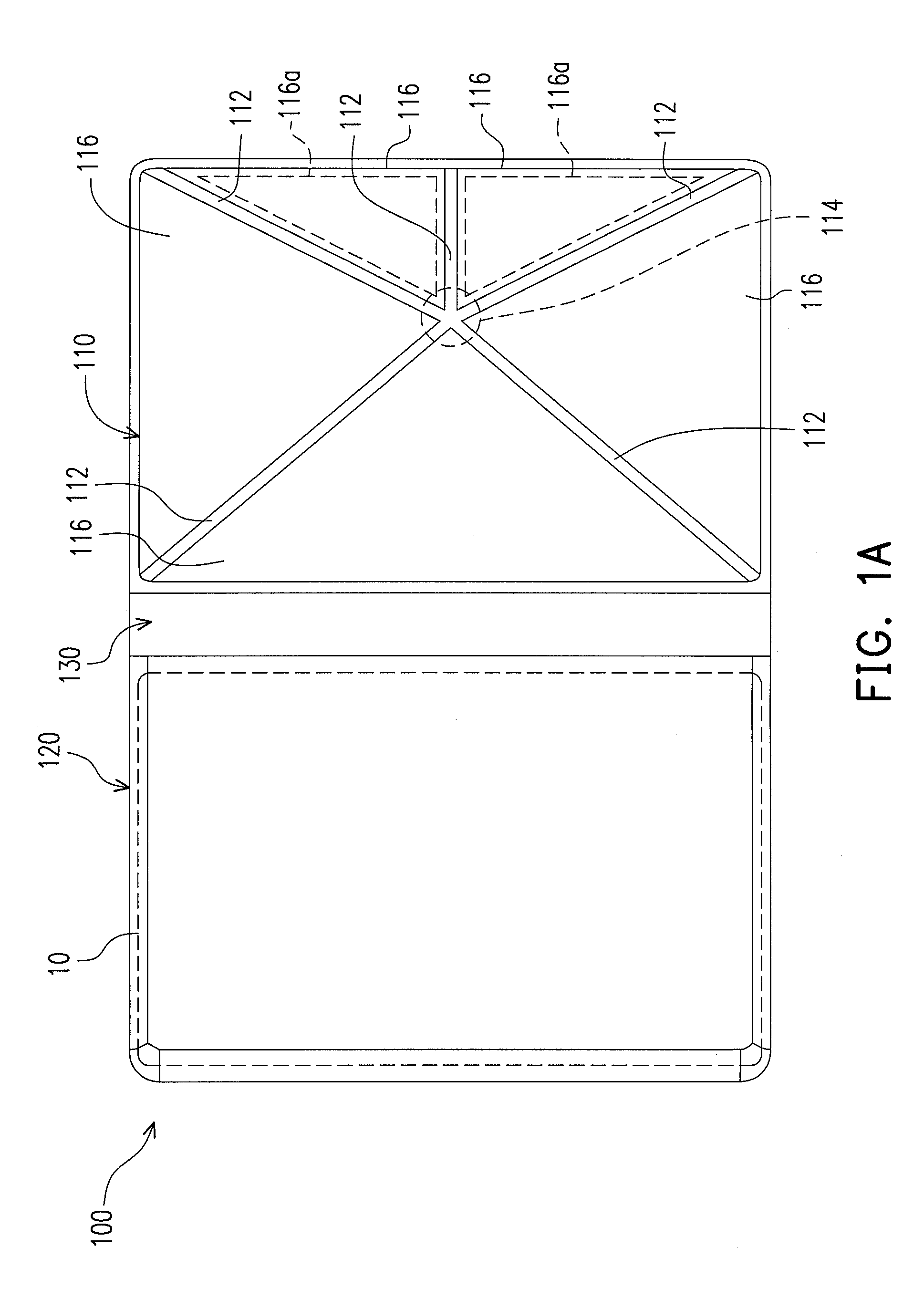
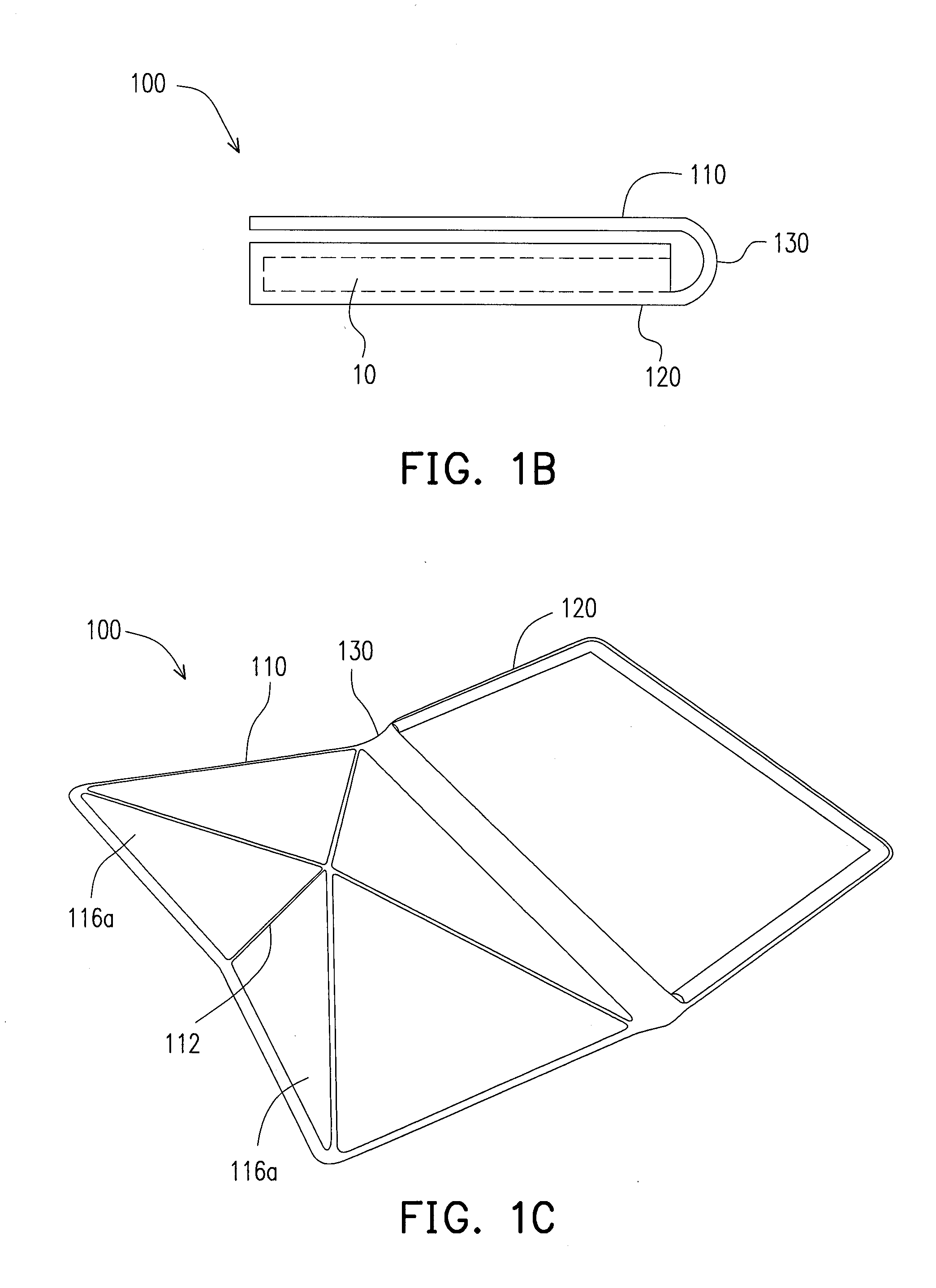
[0027]The disclosure provides a foldable cover 100, adapted to protect or support a portable electronic device 10. FIG. 1A is a top view illustrating a foldable cover according to the disclosure. The foldable cover 100 of the embodiment comprises a supporting unit 110, a fixing unit 120, and a connection member 130. The connection member 130 is connected between the supporting unit 110 and the fixing unit 120.
[0028]In the embodiment, the connection member 130 is a flexible element. However, in other embodiments, the connection member 130 can be a magnetic element or a locking element. The type of the connection member 130 is not limited thereto.
[0029]The supporting unit 110 comprises a plurality of first separations 112, a convergent part 114, and a plurality of first slab-shaped parts 116. Each of the first separations 112 is connected to the convergent part 114, and respectively partitions two adjacent first slab-shaped parts 116. The first slab-shaped parts 116 can be connected t...
second embodiment
[0039]FIG. 2 is a top view illustrating a foldable cover according to the disclosure. The only difference between the embodiment of FIG. 2 and the embodiment of FIG. 1 is the type of the fixing unit. As seen in FIG. 2, the fixing unit 220 of the foldable cover 200 of the embodiment comprises an inner surface 222 and an outer surface 224.
[0040]The inner surface 222 comprises an inner edge 222a, and three outer edges 222b. The inner edge 222a of the inner surface 222 close to the supporting unit 210 is not connected to the outer surface 224, and the other three outer edges 222b are flexibly connected to the outer surface 224. The shape of the inner surface 222 is a hollow rectangle, and the material of the inner surface 222 is a soft material, such as leather.
[0041]When the portable electronic device 10 is put in or taken out of the fixing unit 220, the inner edge 222a of the inner surface 222 of the fixing unit 220 is pulled away from the outer surface 224 of the fixing unit 220. The...
third embodiment
[0042]FIG. 3A is a top view illustrating a foldable cover according to the disclosure. As seen in FIG. 3A, the difference between the foldable cover 300 of the embodiment and the foldable cover 100 of FIG. 1A is that the supporting unit 310 of the embodiment further comprises two second slab-shaped parts 317 and a pair of second separations 318. An end of each of the two second separations 318 are connected to each other. The two separations 318 separate parts of the supporting unit 310, so as to divide out two second slab-shaped parts 317.
[0043]FIG. 3B is a three dimensional schematic view of the foldable cover of FIG. 3A deforming to support the portable electronic device. As seen in FIG. 3B, the bending along the second separations 318 cause the two slab-shaped parts 317 to be located on different surfaces. This way, the center of gravity of the three dimensional structure that is formed by the supporting unit 310 is moved, so as to increase the stability of the three dimensional...
PUM
 Abstract
Description
Claims
Application Information