Eureka AIR delivers breakthrough ideas for toughest innovation challenges, trusted by R&D personnel around the world.

Conveying device and conveying control method

a conveying device and control method technology, applied in the direction of register devices, thin material processing, printing, etc., can solve the problems of many demerits of devices, inability to print one cycle of sub-conveying rollers, and difficulty in realizing higher image quality and throughput, etc., to achieve fast throughput and low cost.

Active Publication Date: 2013-02-21
CANON KK
View PDF1 Cites 3 Cited by
  • Summary
  • Abstract
  • Description
  • Claims
  • Application Information

AI Technical Summary

Benefits of technology

The present invention provides a conveying device and method with a low-cost and high-speed configuration to control the phase of the main conveying roller and the position of the print medium.

Problems solved by technology

According to this configuration, a conveying error is large in delivery of a print medium from the main conveying roller to the sub conveying roller and in conveyance only with the sub conveying roller, and it has been difficult to realize higher image quality and higher throughput.
When the test pattern is printed, the sub conveying roller cannot print one cycle since a length of a single print medium is not sufficient.
However, such realizing device has many demerits such as cost increase caused by provision of a plurality of motors, reduction in a throughput due to operation of the drive switching device, complication of drive transmitting device and control and the like.

Method used


Image

  • Conveying device and conveying control method
  • Conveying device and conveying control method
  • Conveying device and conveying control method

Examples


Embodiment Construction

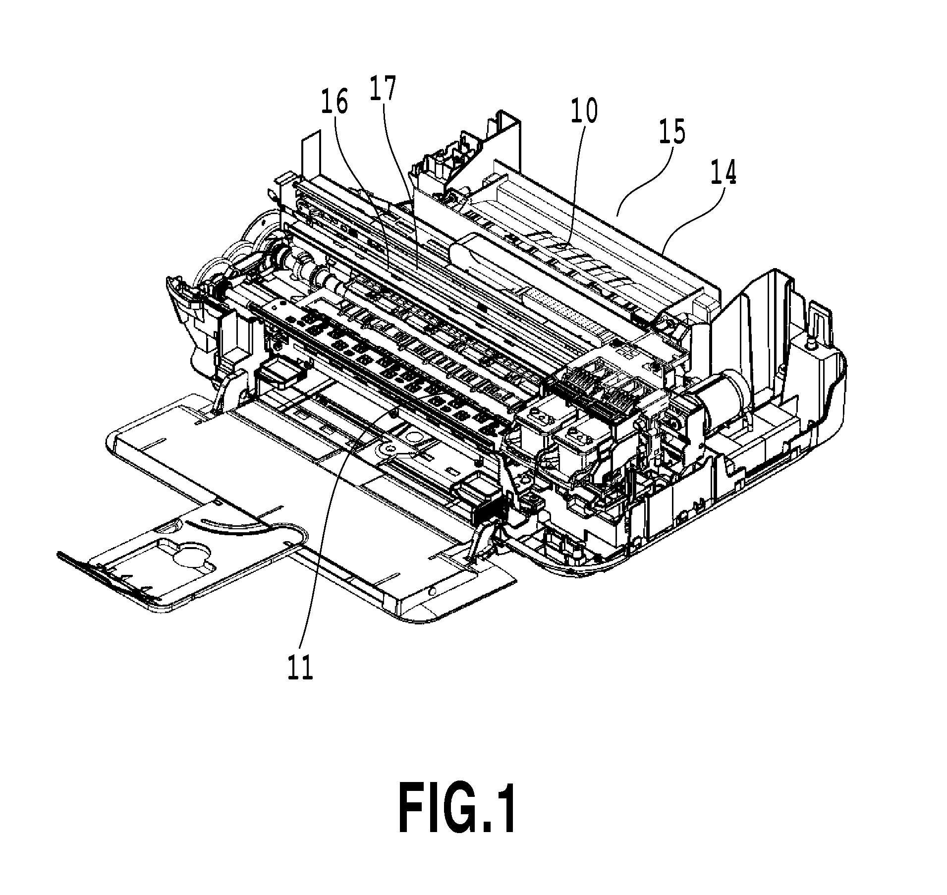
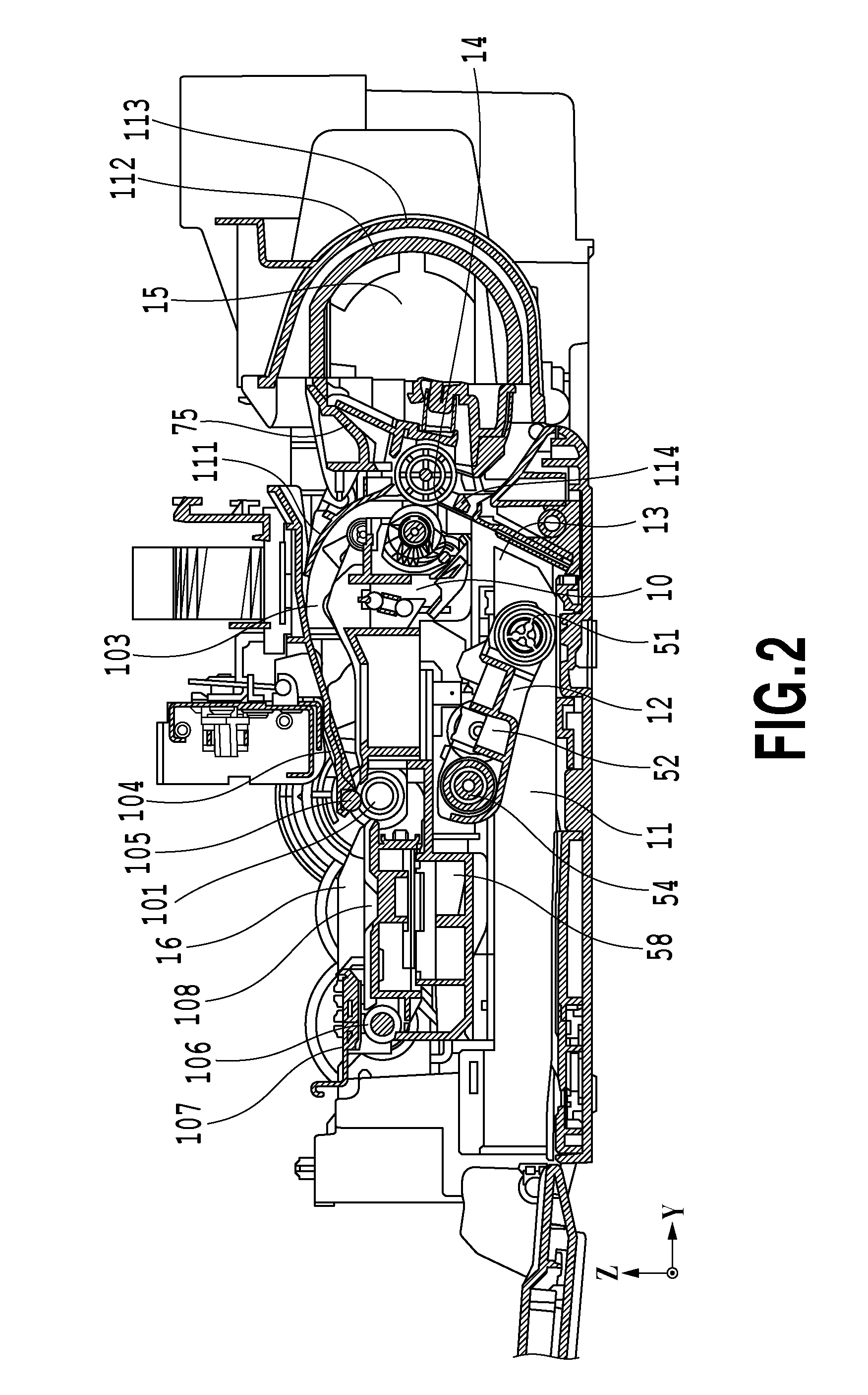
[0043]An embodiment of the present invention will be specifically described below by referring to drawings. The same reference numerals refer to the same or corresponding portions throughout the each drawing. FIG. 1 is a perspective view of one embodiment of a sheet-feeding and conveying device of a printing apparatus in the present invention. FIG. 2 is a longitudinal sectional view of the sheet-feeding and conveying device in FIG. 1. In FIGS. 1 and 2, a sheet-feeding and conveying device 10 is mainly composed of a print-medium loading portion 11, a sheet feeding portion 12, a separation portion 13, a reversing conveying portion 14, a double-sided conveying path 15, and a horizontal conveying portion 16.

(Explanation of Flow of Print Medium in Each Unit)

[0044]A bundle of print mediums set on the print-medium loading portion 11 is separated into a single print medium by the sheet feeding portion 12 and the separation portion 13 and fed to the reversing conveying portion 14. Then, the ...


PUM


Abstract

A conveying device and a conveying control method that can control a phase of a main conveying roller and a position of a print medium with an inexpensive configuration and a fast throughput are provided. For that purpose, an LF roller phase is obtained, phase matching control is performed so that the print medium comes to a desired position when the LF roller is at a desired phase, and skewing of the print medium is corrected by the same control method as the phase matching control.

Description

BACKGROUND OF THE INVENTION[0001]1. Field of the Invention[0002]The present invention relates to a conveying device and a conveying control method and particularly to a conveying device and a conveying control method in which a phase of a conveying roller and a position of a print medium are controlled.[0003]2. Description of the Related Art[0004]Conventionally, in an inkjet printer, a high-accuracy roller in which a metal shaft is coated with a grinding stone has been used as a main conveying roller. As a sub conveying roller also functioning as a discharge roller located on the downstream of the main conveying roller, a rubber roller having an accuracy lower than the main conveying roller and formed by rubber being attached to a metal shaft has been used.[0005]According to this configuration, a conveying error is large in delivery of a print medium from the main conveying roller to the sub conveying roller and in conveyance only with the sub conveying roller, and it has been diffi...

Claims


Application Information

Patent Timeline
Patent Type & Authority Applications(United States)
IPC IPC(8): B41J29/38
CPCB65H7/06B65H9/008B65H2513/53B65H2511/212B65H2511/216B65H2701/1311B65H2220/01B65H2220/03B65H2220/11B65H2220/02B65H2513/52
Inventor TERASHIMA, HIDEYUKI
Owner CANON KK
Why Eureka
Eureka Blog
Learn More