Synchronous motor and control method of synchronous motor

a technology of synchronous motors and control methods, applied in the direction of motor/generator/converter stoppers, electronic commutators, dynamo-electric converter control, etc., can solve the problems of inaccurate detection of synchronous motors, inability to achieve desired rotational speeds, and fluctuation of rotational speed of motors, so as to achieve accurate detection and low acoustic noise

Active Publication Date: 2009-10-15
HITACHI INFORMATION & CONTROL SOLUTIONS LTD +1
View PDF14 Cites 14 Cited by
  • Summary
  • Abstract
  • Description
  • Claims
  • Application Information

AI Technical Summary

Benefits of technology

[0020]According to another preferable embodiment of this invention, an inexpensive synchronous motor can be realized which can be operated with low acoustic noise, whose load condition and speed can be accurately detected from outside the motor housing, and in which plural pieces of information can be transmitted and received without increasing the number of insulating circuits for insulating the internal of the motor from the external thereof.

Problems solved by technology

It was therefore difficult to detect them accurately due to switching surge and unevenness in the characteristics of the circuits for generating and detecting respective commands.
Especially in the operating region of low rotational speeds where command values are small, there were problems that desired rotational speeds cannot be attained and that the rotational speed of motor fluctuates.
Further, since rotational speed pulse signal was of analog quantity, a problem arose that the rotational speed of motor fluctuated so that the rotational speed was detected inaccurately.
Regarding the DUTY command and the torque command mentioned in JP-A-2006-34086, since the magnitudes of the voltages supplied to the motor changed in response to the variation of the DC voltage, the rotational speed of the motor changed so that the beats of 100 or 120 Hz created a problem of acoustic noise during operation and a problem of decreased efficiency due to load fluctuation.
It was therefore difficult to detect from outside of the motor housing the condition of the motor and the condition of the load such as a fan attached to the motor.
For example, it was difficult to detect from outside the motor housing the degree of the accumulation of dirt on the blades of a fan attached to the motor.
Furthermore, since the condition of the load was detected with the number of the electrical connections between the internal and external of the motor kept minimum, the current detectors, installed outside the motor, were located far from the optimal positions for detection so that there arose a problem of degradation of accuracy in current detection and a problem of increased cost due to the necessity of circuits for insulating the current detectors from the motor.

Method used


Image

  • Synchronous motor and control method of synchronous motor
  • Synchronous motor and control method of synchronous motor
  • Synchronous motor and control method of synchronous motor

Examples


embodiment 1

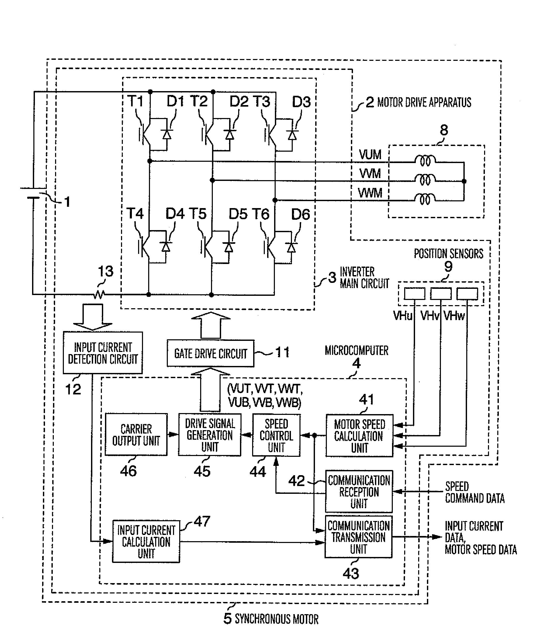
[0052]FIG. 1 shows in block diagram the overall circuit configuration of a synchronous motor as a first embodiment of this invention. The motor drive apparatus 2 shown with the first embodiment of this invention in FIG. 1 is very suitable for use as a drive means for the fan motor of the indoor or outdoor unit of an air conditioner, or for a hot water supplier.

[0053]As shown in FIG. 1, a DC power source 1 supplies power to a motor drive circuit 2 for a synchronous motor. The supplied power has a high voltage of, for example, about 141˜450 volts that is available from a battery or a commercial converter which can rectify and smooth AC power from the commercial power line. An inverter main circuit 3 consists of three pairs of switching elements (T1 and T4, T2 and T5, and T3 and T6) connected between the DC terminals, each pair of switching elements being connected in series with each other, and the connection point between the series connected switching elements providing each termina...

embodiment 2

[0092]FIG. 15 shows in block diagram the overall circuit configuration of a synchronous motor as a second embodiment of this invention. In FIG. 15, constituents similar to those shown in FIG. 1 are indicated at the same reference symbols as in FIG. 1, and the description thereof will be omitted. Only constituents that operate differently will be described in the following.

[0093]This second embodiment differs from the first embodiment in that this embodiment additionally includes an input voltage detection circuit 14, an input voltage calculation unit 48, an input power calculation unit 49, and a communication transmission unit 54.

[0094]In FIG. 15, the input voltage detection circuit 14 serves to detect the voltage developed between the positive and negative terminals of the DC power source 1, and is realized by, for example, a voltage divider consisting of resistors. The input voltage calculation unit 48 converts the detected value of voltage, that is an analog quantity, representin...

embodiment 3

[0104]FIG. 19 shows in block diagram the overall circuit configuration of a synchronous motor as a third embodiment of this invention. In FIG. 19, constituents similar to those shown in FIG. 1 are indicated at the same reference symbols as in FIG. 1, and the description thereof will be omitted. Only constituents that operate differently will be described in the following.

[0105]This embodiment differs from the first embodiment described above in that it includes a motor current detection unit 15, an input current calculating unit 50 and a communication transmission unit 55.

[0106]As shown in FIG. 19, the motor current detection unit 15 serves to detect the current flowing through a resistor R10 disposed between the switching element T4 on the negative side of the inverter main circuit 3 and the ground (hereafter referred to as U-phase current), and the current flowing through a resistor R11 disposed between the switching element T5 on the negative side of the inverter main circuit 3 a...


PUM


Abstract

A synchronous motor including therein a three-phase inverter and position sensors, having a unit for calculating a digital input current value from the analog output of an input current detection circuit that detects the input current flowing into the DC input terminal of the three-phase inverter, and a digital feedback speed control unit for adjusting the amplitudes and frequency of the AC voltages outputted from the three-phase inverter in such a manner that the motor speed calculated by a motor speed calculation unit 41 on the basis of the outputs of the position sensors approaches a speed command value received by a communication reception unit from outside the synchronous motor. The synchronous motor further includes therein a communication transmission unit for transmitting the input current value and the motor speed to outside the synchronous motor.

Description

BACKGROUND OF THE INVENTION[0001]This invention relates to a synchronous motor for use in an air conditioner and a hot water supplier, and to a method for controlling the synchronous motor.[0002]Synchronous motors have been used recently as fan motors for use in air conditioners and hot water suppliers since they can be controlled over a wide range of speeds, their energy consumption is economical, and they can be operated with low acoustic noise. Such a synchronous motor is usually driven by sinusoidal waves generated by a motor drive circuit installed in the housing of the synchronous motor.[0003]Usually, a synchronous motor is provided with Hall ICs, which are inexpensive and simple in configuration, used as position sensors and an inverter main circuit. The Hall ICs detect the positions of the magnetic poles of the synchronous motor. The switching elements in the inverter main circuit are controlled on the basis of the information on the positions of the magnetic poles, and the ...

Claims


Application Information

Patent Timeline
Patent Type & Authority Applications(United States)
IPC IPC(8): H02P6/16H02P6/08H02P6/06
CPCH02P6/16H02P6/08H02P6/10
Inventor MAEDA, DAISUKESAKURAI, KENJIHASEGAWA, HIROYUKISHIRAHAMA, HIDEFUMIMISHIMA, MITSUHIRO
Owner HITACHI INFORMATION & CONTROL SOLUTIONS LTD
Why Eureka
Try Eureka