Short-range radar and control method thereof

a short-range radar and control method technology, applied in the direction of instruments, antenna feed intermediates, antennas, etc., can solve the problems of carrier leakage power not being ignored, unable to be completely stopped, and unable to reduce the gain in this band, so as to prevent the radiowave emission to the rr prohibited band and the srd band more positively

Inactive Publication Date: 2010-10-12
PANASONIC CORP +1
View PDF19 Cites 15 Cited by
  • Summary
  • Abstract
  • Description
  • Claims
  • Application Information

AI Technical Summary

Benefits of technology

[0029]The present invention has been achieved in view of the situation described above, and an object thereof is to provide a short-range radar having an inexpensive configuration and a control method thereof in which the interference with the RR prohibited band and the SRD band is prevented while at the same time complying with the stipulated spectrum mask.

Problems solved by technology

The aforementioned configuration in which the short pulse wave Pb is generated by intermittently turning on / off the switch circuit 2 inserted into the path of the carrier signal S, however, poses the problem that the carrier signal output, though ideally completely stopped during the turn-off state of the switch circuit 2, cannot be actually stopped completely due to the leak of the switch circuit 2.
On the average, therefore, the power of the carrier leak is not ignorable.
Especially, it is difficult to prevent the leak of the carrier signal in the UWB of high frequency.
As a result, the radar search range is narrowed, and it becomes difficult to detect an obstacle of a low reflectivity as an object existing in the space.
In the case where the leak component S′ is large as in the aforementioned case, therefore, the output of the short pulse wave Pb for the regular transmission timing is required to be set at a correspondingly low level, resulting in a considerable limitation of the search range of the radar.
Actually, therefore, it is very difficult to suppress the emission power density to −61.3 dBm or less specified by the latest spectrum mask.
This increases the size along the height and makes an application as an on-vehicle radar difficult.
Even in the case where a switch capable of achieving a high isolation in the very high frequency band described above can be realized, however, such a switch is very expensive and very difficult to employ for the on-vehicle radar used by common people or visually handicapped persons.

Method used


Image

  • Short-range radar and control method thereof
  • Short-range radar and control method thereof
  • Short-range radar and control method thereof

Examples


first embodiment

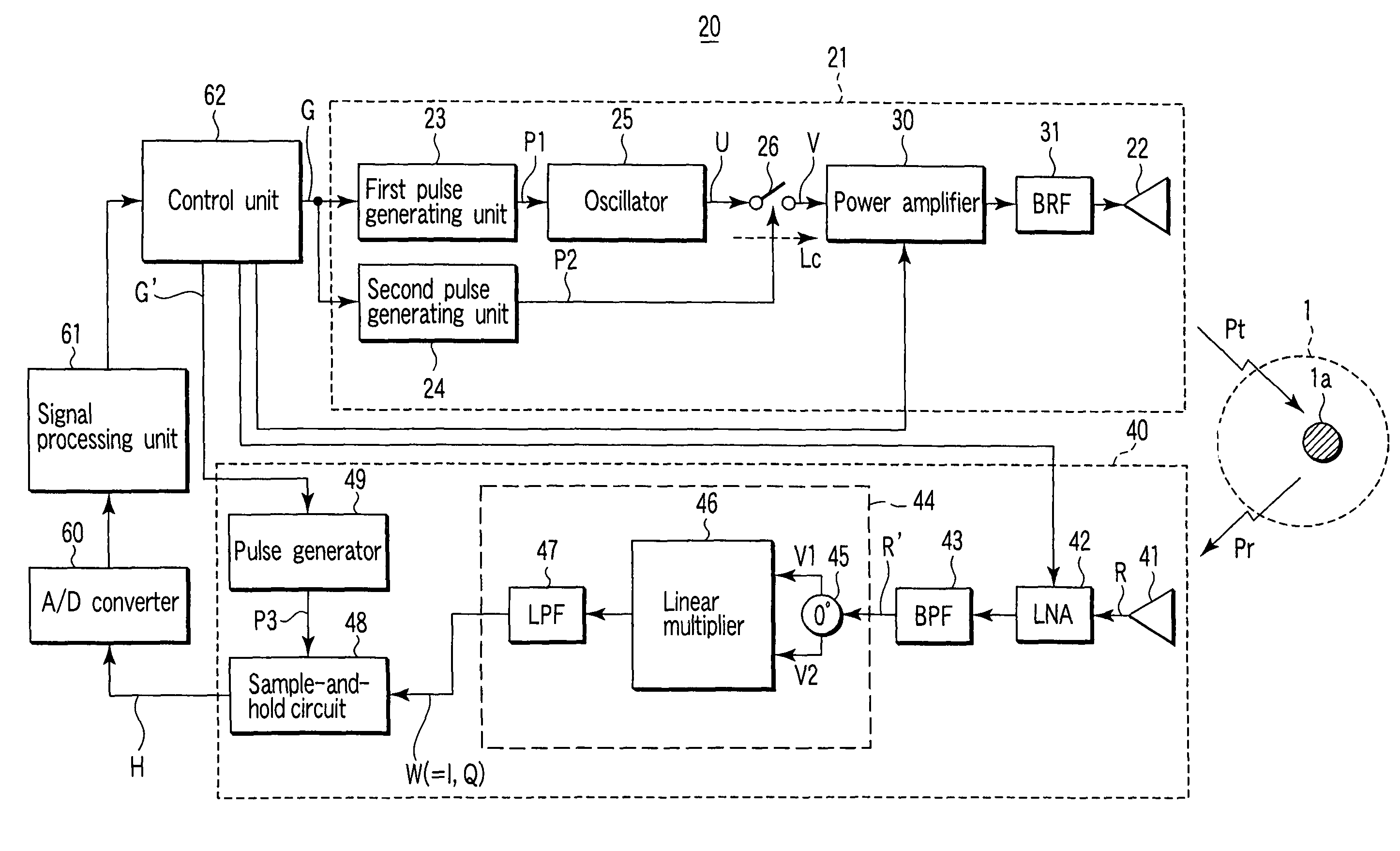
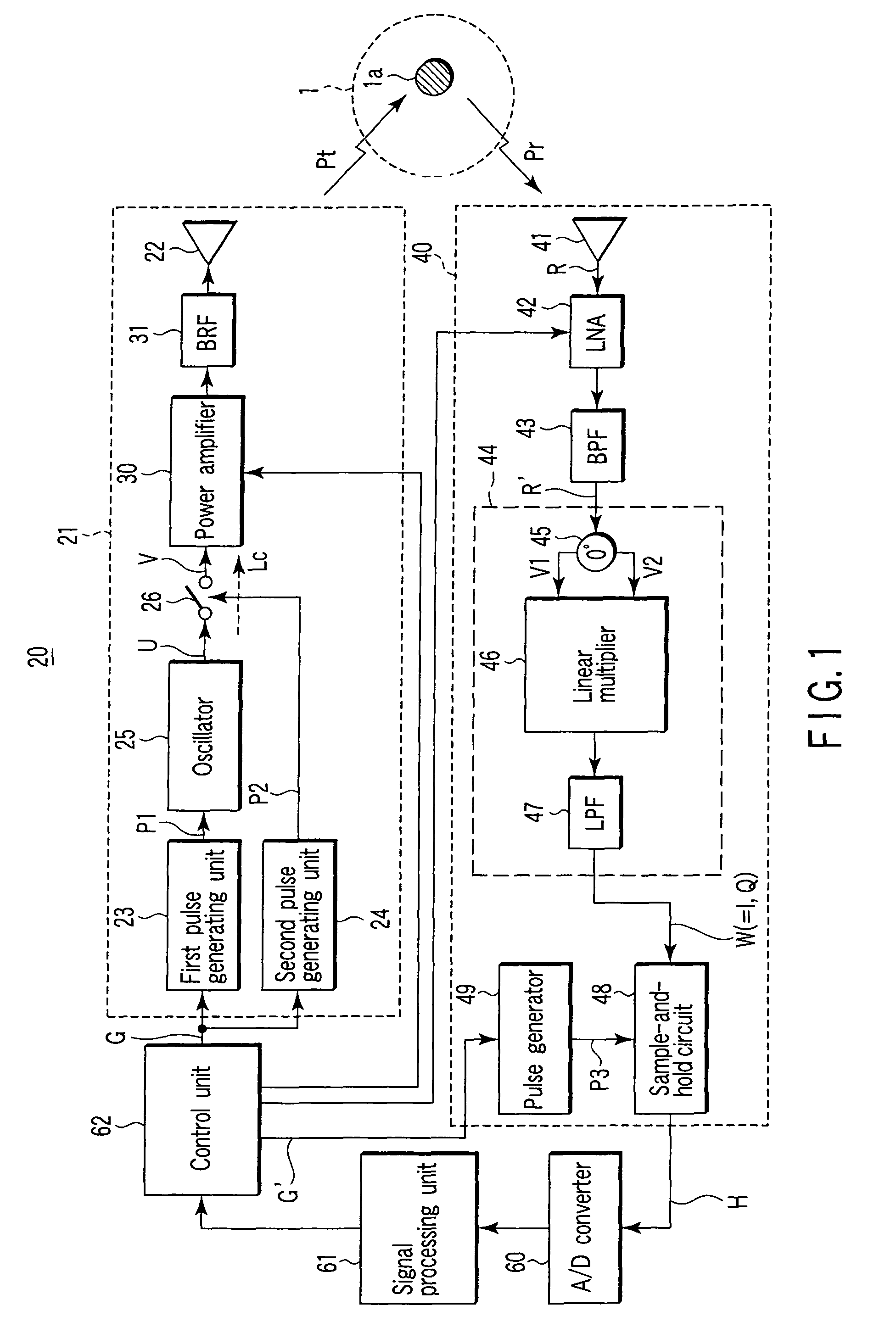
[0183]FIG. 1 is a block diagram showing the general configuration of a short-range radar and a control method thereof according to a first embodiment of the invention.

[0184]A short-range radar 20 according to this invention basically includes: a transmitting unit 21 for emitting a predetermined short pulse wave Pt from a transmission antenna 22 into a space 1; a receiving unit 40 for executing a process of receiving a reflected wave Pr from an object 1a existing in the space 1; and a signal processing unit 61 for executing a process of analyzing the object 1a based on the output signal from the receiving unit 40, wherein the transmitting unit 21 includes: a first pulse generating unit 23 for outputting a first pulse P1 having a width Tc longer than the width of the short pulse wave Pt in a predetermined period Tg; a second pulse generating unit 24 for outputting a second pulse P2 having the width corresponding to the width of the short pulse wave Pt at a timing upon the lapse of a p...

second embodiment

[0293]FIG. 20A is a block diagram showing the general configuration of a second embodiment using the short-range radar and the control method thereof according to the invention.

[0294]Incidentally, in FIG. 20A, the parts configured similarly to those of the short-range radar according to the first embodiment shown in FIG. 1 described above are designated by the same reference numerals, respectively, and not described again.

[0295]According to the first embodiment described above, the linear multiplier 46 of square detection type requiring no local signal is employed as the detection circuit 44 of the receiving unit 40. According to the second embodiment, in contrast, a quadrature demodulator 51 of quadrature demodulation type requiring the local signal is employed as the detection circuit 4 of the receiving unit 40.

[0296]The use of this quadrature demodulator 51 of quadrature demodulation type requires the local signal equal in frequency to the receiving signal, and the burst carrier ...

third embodiment

[0301]FIG. 20B is a block diagram showing the general configuration of a third embodiment using the short-range radar and the control method thereof according to this invention.

[0302]Incidentally, in FIG. 20B, the parts configured similarly to those of the short-range radar according to the first embodiment shown in FIG. 1 described above are designated by the same reference numerals, respectively, and not explained any more.

[0303]The second embodiment described above is applicable to a case in which the exploration range of the short-range radar is not very long, while the third embodiment is used in a case where the exploration range of the short-range radar is long.

[0304]In the case where the exploration range of the short-range radar is long, the output period Tc of the burst carrier U output from the oscillator 25 of the transmitting unit 21 is lengthened, thereby posing the problem that the carrier leak is increased.

[0305]To obviate this problem, according to the third embodim...


PUM


Abstract

A transmitting unit of a short-range radar includes a first pulse generating unit, a second pulse generating unit, an oscillator and a switch, and while complying with the spectrum mask specified for a UWB short-range radar, emits a predetermined short pulse wave not interfering with the RR prohibited band or the SRD band into the space. The first pulse generating unit outputs a first pulse having the width larger than the width of the short pulse wave in a predetermined period. The second pulse generating unit outputs a second pulse having the width corresponding to the width of the short pulse wave during the period when the first pulse generating unit outputs the first pulse. The oscillator oscillates only during the period when the first pulse generating unit outputs the first pulse, and the switch is turned on and passes the output signal from the oscillator only during the period when the second pulse generating unit outputs the second pulse, thereby to emit the output signal from the switch into the space as the predetermined short pulse wave.

Description

CROSS-REFERENCE TO RELATED APPLICATIONS[0001]This application is a U.S. National Phase Application under 35 USC 371 of International Application PCT / JP2007 / 054074 filed Mar. 2, 2007.TECHNICAL FIELD[0002]The present invention relates to a short-range radar and a control method thereof, and particularly to a short-range radar using UWB (Ultra Wideband) of 22 to 29 GHz employing a technique exactly complying with the stipulation of the International Radio Communication Regulations (RR) and a control method thereof.BACKGROUND OF THE INVENTION[0003]Recently, a short-range radar using UWB has nearly come to find practical application for use on an automotive vehicle and for visually handicapped persons.[0004]In the short-range radar of this type using UWB, like in the ordinary radar, the short pulse wave is emitted from the antenna of a transmitting unit into the space, and a receiving unit receives the wave reflected from an object existing in the space thereby to analyze the object.[000...

Claims


Application Information

Patent Timeline
Patent Type & Authority Patents(United States)
IPC IPC(8): G01S13/10G01S7/28G01S13/00H04B1/69
CPCG01S7/282G01S13/106H01Q9/27H01Q21/061H04B1/7174G01S13/0209
Inventor TESHIROGI, TASUKUEJIMA, MASANORI
Owner PANASONIC CORP
Why Eureka
Try Eureka