
Picture processing apparatus, picture recording apparatus, method and program thereof

a picture processing and picture recording technology, applied in the field of picture processing apparatus, picture recording apparatus, method and program thereof, can solve the problems of raising the cost of the entire system, difficulty in intuitively distinguishing pictures, and retaining the portability or control of production costs, so as to achieve low cost and inexpensive apparatus configuration

Inactive Publication Date: 2008-11-06
FUJIFILM CORP
View PDF3 Cites 15 Cited by
  • Summary
  • Abstract
  • Description
  • Claims
  • Application Information

AI Technical Summary

Benefits of technology

[0018]Therefore, the present invention realizes picture recording in simple configuration such that a user can easily and intuitively identify a minified picture of a multi-view picture from among minified pictures of pictures being taken. The present invention also prevents recording of an ineffective multi-view picture without a stereo effect.
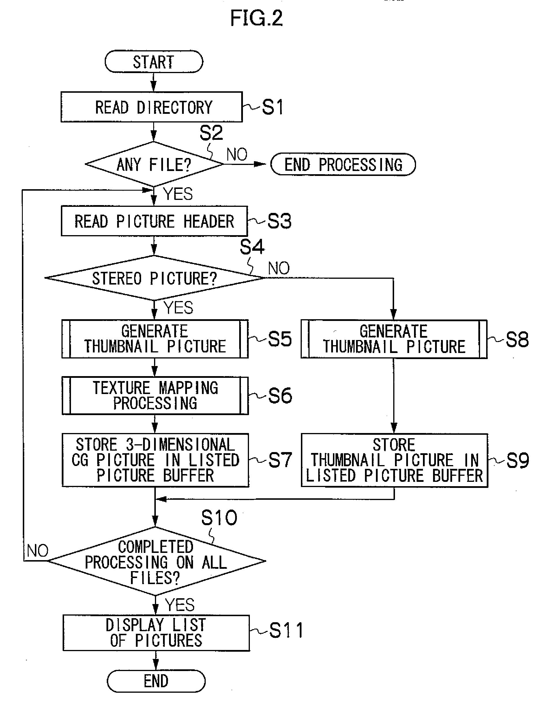
[0060]According to the present invention, a minified picture subjected to the 3-dimensional computer graphic processing, more preferably, a minified picture containing a subject face region subjected to the 3-dimensional computer graphic processing as a minified picture of a multi-view picture is recorded in association with the primary picture. On the other hand, a simple minified picture as a minified picture of a single view picture, a multi-view picture not containing a detected face or multi-view picture containing a subject at long range is recorded in association with a primary picture. The minified picture of the multi-view picture has been subjected to the 3-dimensional computer graphic processing so that the difference between the minified picture of the multi-view picture and the minified picture of the single-view picture can be clearly seen. Additionally, it is not necessary to use a special graphical approach to display the minified picture of the multi-view picture, realizing inexpensive apparatus configuration.

Problems solved by technology

However, it is difficult to intuitively differentiate the pictures.
As such, it has a drawback that it raises a cost of the entire system.
Particularly, the inevitable arrangement of such a special display apparatus in portable equipment such as a digital camera causes a serious problem in retention of the portability or control of a production cost.
Also, Japanese Patent Application Laid-Open No. 2003-51872 has a problem in that a subject at infinity cannot be given a stereoscopic vision effect.

Method used


Image

  • Picture processing apparatus, picture recording apparatus, method and program thereof
  • Picture processing apparatus, picture recording apparatus, method and program thereof
  • Picture processing apparatus, picture recording apparatus, method and program thereof

Examples


first embodiment

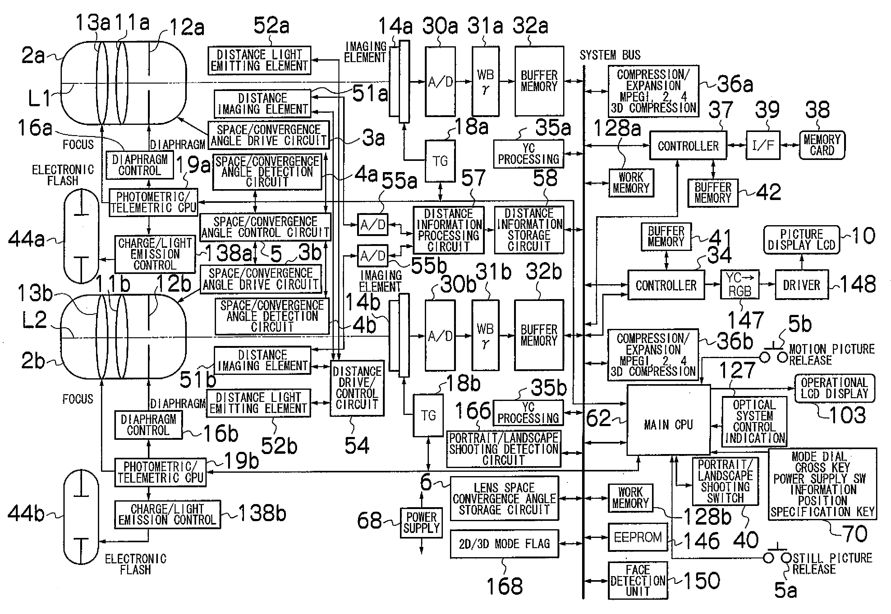
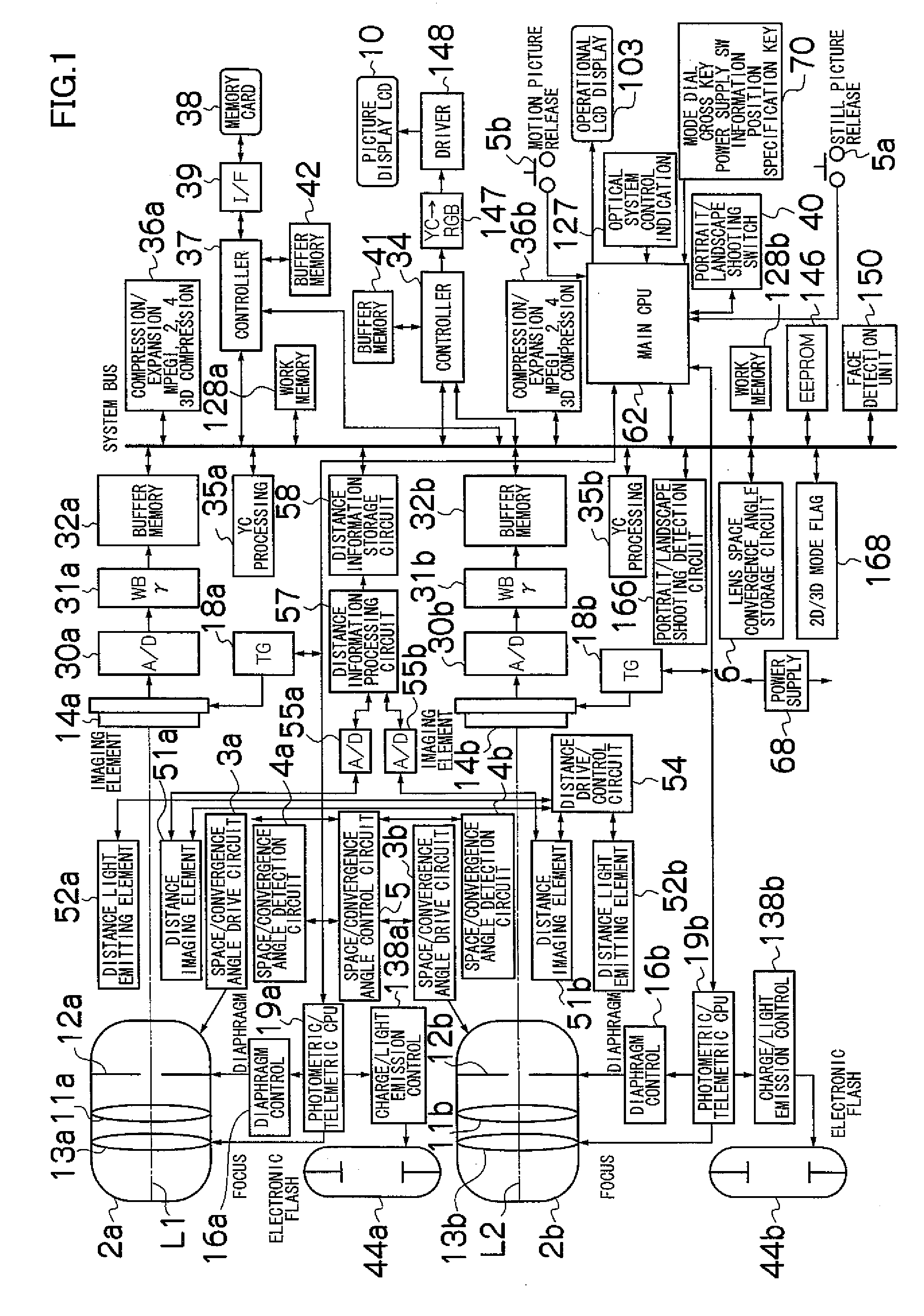
[0080]FIG. 1 shows the electric configuration of a pantoscopic camera 1. Lens optical axes L1 and L2 of first and second imaging units 2a and 2b are arranged to be parallel or at a pre-determined angle to each other.

[0081]The first imaging unit 2a comprises a first zoom lens 11a, a first diaphragm 12a, a first focus lens 13a and a first image sensor 14a arranged along the lens optical axis L1. The first diaphragm 12a connects to a diaphragm control unit 16a, while the first image sensor 14a connects to a timing generator (TG) 18a. The operation of the first diaphragm 12a and the first focus lens 13a is controlled by a photometric / telemetric CPU 19a. The operation of the TG 18a is controlled by a main CPU 62.

[0082]The camera 1 is provided with an operation unit 70 for various operation when a user uses the camera 1. The operation unit 70 comprises a power supply switch which turns on the power supply to actuate the camera 1, a mode dial to select stereographic (3D) shooting, plane (2...

second embodiment

[0131]FIG. 5 shows another example of the listed picture display processing executed by the main CPU 62. Herein, thumbnail pictures of multi-view pictures containing faces being taken are replaced to special samples.

[0132]S21 to S24 are similar to S1 to S4.

[0133]At S25, the face detection unit 150 is instructed to extract faces from one or both of the multi-view pictures. In response to the instruction from the main CPU 62, the face detection unit 150 attempts to detect a face region from a picture for a left eye or a picture for a right eye stored in a picture file.

[0134]At S26, it is judged whether or not the face detection unit 150 can detect a face region. If a face region can be detected, the flow proceeds to S27; if a face region cannot be detected, the flow proceeds to S29.

[0135]At S27, a sample 3-dimensional thumbnail picture which symbolizes being a multi-view picture containing a face being shot is retrieved from the EEPROM 146.

[0136]At S28, the retrieved sample is stored ...

third embodiment

[0141]FIG. 7 shows another example of the listed picture display processing executed by the main CPU 62. Herein, thumbnail pictures of flash multi-view pictures are replaced to special samples.

[0142]S41 to S44 are similar to S1 to S4.

[0143]At S45, flash firing information is obtained from a picture file to identify the ON or OFF state of the electronic flashes 44a and 44b at the picture recording. The flash firing information is, for example, information stored in a “Flash” tag of an Exif file.

[0144]At S46, the ON or OFF state of the electronic flashes 44a and 44b is judged at the shooting based on the flash firing information. If the electronic flashes 44a and 44b are at the ON state at the shooting, the flow proceeds to S47; if they are at the OFF state, the flow proceeds to S49.

[0145]At S47, a sample 3-dimensional thumbnail picture to symbolize to be a multi-view picture is retrieved from the EEPROM 146. The sample is given a stereo effect due to the 3-dimensional CG processing s...


PUM


Abstract

The present invention realizes picture recording in simple configuration such that a user can easily and intuitively identify a minified picture of a multi-view picture from among minified pictures of pictures being taken. A 3-dimensional thumbnail picture is created by performing 3-dimensional CG processing on a multi-view picture thumbnail picture, and a thumbnail picture is created from a normal picture and recorded in association with a primary picture. The 3-dimensional CG thumbnail picture X is given a stereoscopic effect as a result of the 3-dimensional CG graphic processing so that the difference from a normal 2-dimensional thumbnail Y is clear at a glance. Consequently, a viewer can readily recognize the picture X as a minified picture of a multi-view picture without using a special apparatus to realize a graphical approach.

Description

BACKGROUND OF THE INVENTION[0001]1. Field of the Invention[0002]The present invention relates to display of a list of minified pictures of a multi-view picture and a single-view picture. The present invention also relates to recording of minified pictures of a multi-view picture and a single-view picture.[0003]2. Description of the Related Art[0004]In a general stereo picture display system, a picture drawn from a viewpoint of a right eye and a picture drawn from a viewpoint of a left eye are presented to a right eye and a left eye, respectively. Normally, in such two pictures from viewpoints of a right eye and a left eye (hereinafter, referred to as a multi-view picture), objects at a distant position from the viewpoints are viewed to be approximately same because the lines of sight from both eyes are approximately parallel so that the pictures are drawn at the approximately same position. On the contrary, objects at a near position to the viewpoints are viewed to be different beca...

Claims


Application Information

Patent Timeline
Patent Type & Authority Applications(United States)
IPC IPC(8): H04N13/02G06T15/00G06K9/00H04N13/04G06T15/20H04N13/239H04N13/30
CPCG06K9/3266G06T15/205H04N13/0029H04N13/0055H04N13/0239H04N13/04H04N13/189H04N13/30H04N13/239H04N13/139G06V20/635
Inventor MIYAKE, IZUMI
Owner FUJIFILM CORP
Learn More