Optical fiber thermometer and temperature-compensated optical fiber sensor

a technology of optical fiber and temperature compensation, which is applied in the direction of instruments, heat measurement, fluid pressure measurement, etc., can solve the problems of reducing the precision of measuring, reducing the accuracy of measuring, and expensive measuring devices, so as to achieve constant temperature measurement capabilities, increase the accuracy of measuring devices, and reduce the cost of measuring devices

Inactive Publication Date: 2009-08-13
THE FUJIKURA CABLE WORKS LTD
View PDF4 Cites 14 Cited by
  • Summary
  • Abstract
  • Description
  • Claims
  • Application Information

AI Technical Summary

Benefits of technology

[0035]The optical fiber thermometer of the invention includes one optical fiber for projection that relays light from the light source to a measuring unit, two optical fibers for light-reception that relay light reflected from a reflecting face of a mirror provided at the measuring unit to two light-receiving units, and an arithmetic processing circuit that calculates the pressure of the measuring unit from the ratio of electrical signals from the two light-receiving units; end surfaces of three optical fibers arranged to face the reflecting face being fixed such that an angle θ between the longitudinal direction of the optical fibers and the normal to the reflecting face is not zero, the two optical fibers for light-reception being parallel, fixing angles between each of them and the optical fiber for projection being symmetrical based on the normal to the reflecting face as a reference, and each of the optical fibers being a single-mode fiber at the wavelength being used,. Therefore, with an inexpensive device configuration, temperature can be precisely measured based on changes in light power. The measuring precision can be further increased by making the angle θ equal to or greater than 8°.
[0036]Further, a three-core array for measuring temperature is formed by fixing measuring unit-side ends of the optical fiber for projection and the two optical fibers for light-reception to a V-groove array substrate, and the measuring unit is composed by fixing the three-core array for measuring temperature and said mirror to an array-fixing base material, Therefore, it is possible to provide an easy-to-manufacture and inexpensive optical fiber thermometer that has constant temperature-measuring capabilities.
[0037]Further, since the linear expansion coefficient of the base material of the mirror

Problems solved by technology

In this type of optical sensor, when the target being measured is a physical quantity other than temperature, changes in characteristics caused by changes in temperature can reduce the precision of the measuring.
However, since a principle of these conventional techniques is to measure wavelength changes and the modulation component of light, these measuring devices are expensive Other factors making them expensive are that they require a variable-frequency light source to realize temperature-compensation (Patent Document 1), that they require a special structure (Patent Document 4), and so on.
As a result, the configurations of Patent Documents 2, 5, and 6 are problematic in that change in the light-branching ratio affects the measurement value, and thus reduces the measuring precision.
To avoid this problem, Patent Document 5 attempts to stabilize the measuri

Method used


Image

  • Optical fiber thermometer and temperature-compensated optical fiber sensor
  • Optical fiber thermometer and temperature-compensated optical fiber sensor
  • Optical fiber thermometer and temperature-compensated optical fiber sensor

Examples


Embodiment Construction

[0086]An embodiment of the invention will be explained with reference to the drawings.

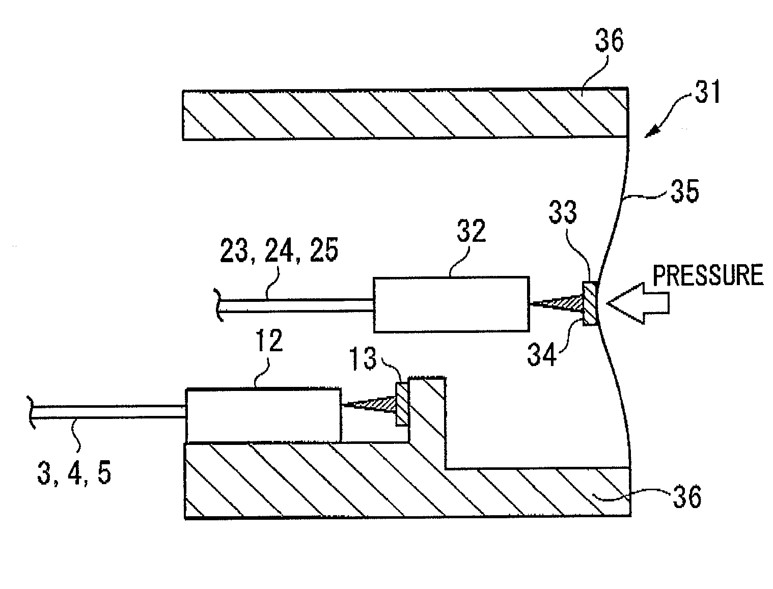
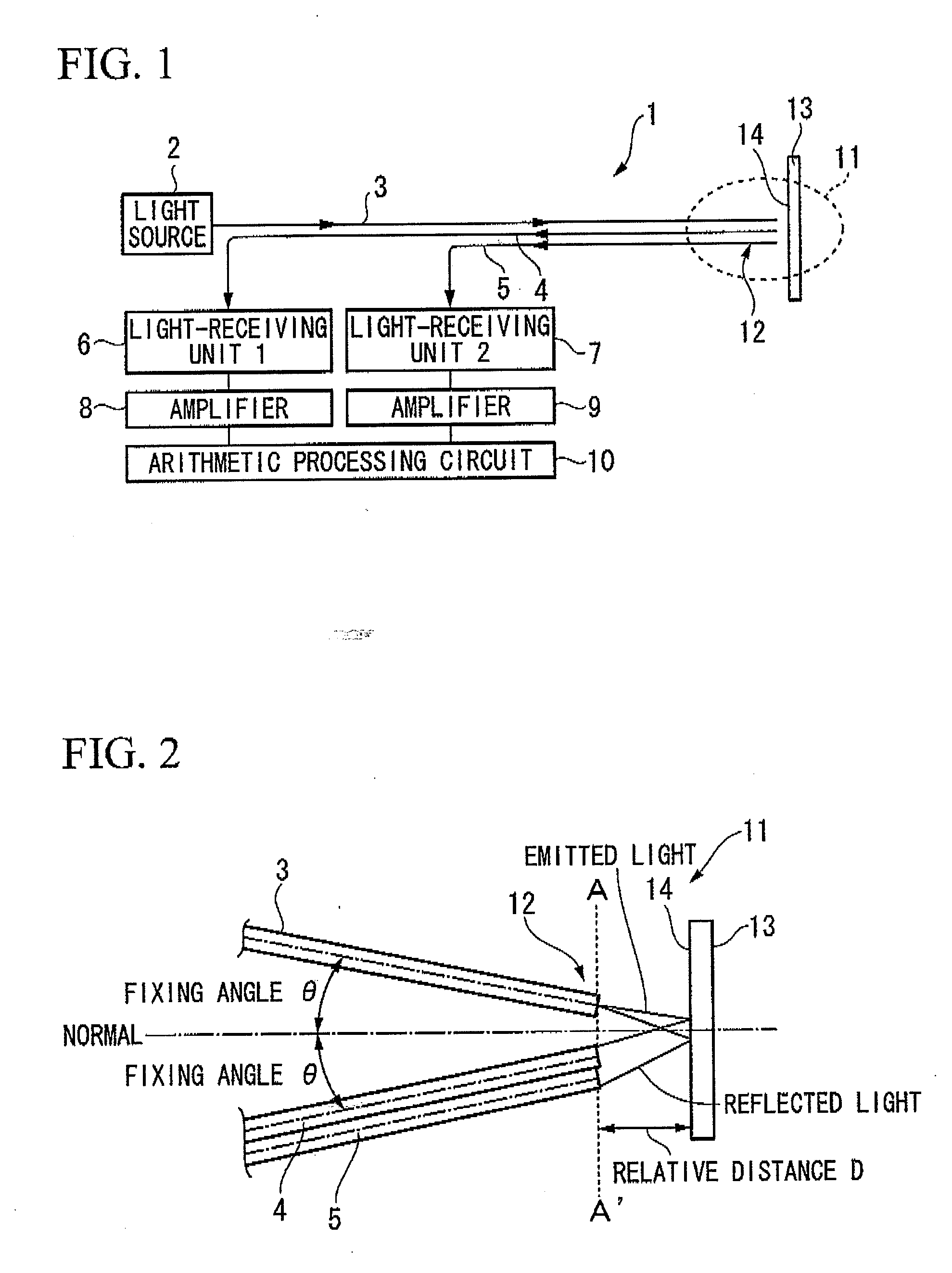
[0087]FIGS. 1 to 2 and FIGS. 7 to 8 are diagrams of an embodiment of an optical fiber thermometer of the invention, FIG. 1 being a configuration diagram of an optical thermometer, FIG. 2, an enlarged configuration diagram of a measuring unit of the same. optical fiber thermometer, FIG. 7, a cross-sectional view along the line A-A′ of FIG. 2, and FIG. 8, a side view of the configuration of a measuring unit. In these diagrams, reference numeral 1 represents an optical fiber thermometer, 2 represents a light source, 3 represents an optical fiber for projection, 4 and 5 represent optical fibers for light-reception, 3A to 5A represent cores, 6 and 7 represent light-receiving units, 8 and 9 represent amplifiers, 10 represents an arithmetic processing circuit, 11 represents a measuring unit, 12 represents a three-core array for measuring temperature, 13 represents a mirror, 14 represents a reflecting face...


PUM


Abstract

This optical fiber thermometer includes one optical fiber for projection that relays light from the light source to a measuring unit, two optical fibers for light-reception that relay light reflected from a reflecting face of a mirror provided at the measuring unit to two light-receiving units, and an arithmetic processing circuit that calculates the pressure of the measuring unit from the ratio of electrical signals from the two light-receiving units; end surfaces of three optical fibers arranged to face the reflecting face being fixed such that an angle θ between the longitudinal direction of the optical fibers and the normal to the reflecting face is not zero, the two optical fibers for light-reception being parallel, fixing angles between each of them and the optical fiber for projection being symmetrical based on the normal to the reflecting face as a reference, and each of the optical fibers being a single-mode fiber at the wavelength being used, According to this invention, it is possible to provide an optical fiber thermometer that is inexpensive and can measure temperature with high precision, and a temperature-compensated optical fiber sensor that uses the optical fiber thermometer in compensating measurement error due to temperature-change, and can achieve highly precise measuring.

Description

[0001]This application is a continuation application based on a PCT Patent Application No. PCT / JP2007 / 070335, filed Oct. 18, 2007, whose priority is claimed on Japanese Patent Application No. 2006-284027, filed Oct. 18, 2006. The contents of both the PCT Application and the Japanese Application are incorporated herein by reference.TECHNICAL FIELD[0002]The present invention relates to an optical fiber thermometer and a temperature-compensated optical sensor using the thermometer, and more particularly relates to a sensor that uses an optical thermometer to compensate measurement error resulting from temperature-change, and can measure various types of physical quantities, such as pressure, with high precisionBACKGROUND ART[0003]An optical sensor that uses an optical fiber to guide light to a measuring unit, and senses changes in the optical condition at the measuring unit, does not use electricity in the measuring unit; it therefore has advantages such as offering excellent resistanc...

Claims


Application Information

Patent Timeline
IPC IPC(8): G01L19/04G01K11/00G06F15/00
CPCG01D5/268G01D5/30G01L19/0092G01L9/0077G01K11/12
Inventor SAKAMOTO, AKIRAHORIMOTO, KEIICHINOGUCHI, YOSHIKIYO
Owner THE FUJIKURA CABLE WORKS LTD
Why Eureka
Try Eureka